XMatrix DMX512 Interface: a lighting console drives the motor
XMatrix is the software system of XMSP. This page is the DMX512 function, code DMX512. A console or a media server can add the motor to a fixture library so a fader drives position and speed. An MSP controller can also turn XMatrix run data into a DMX bus.
- Slave / masterThree roles
- P / PV / PPV / VChannel modes
- Console directOn the whole range
- Loss-of-signal behaviorDefault: return to 0 after 5 seconds
What it does
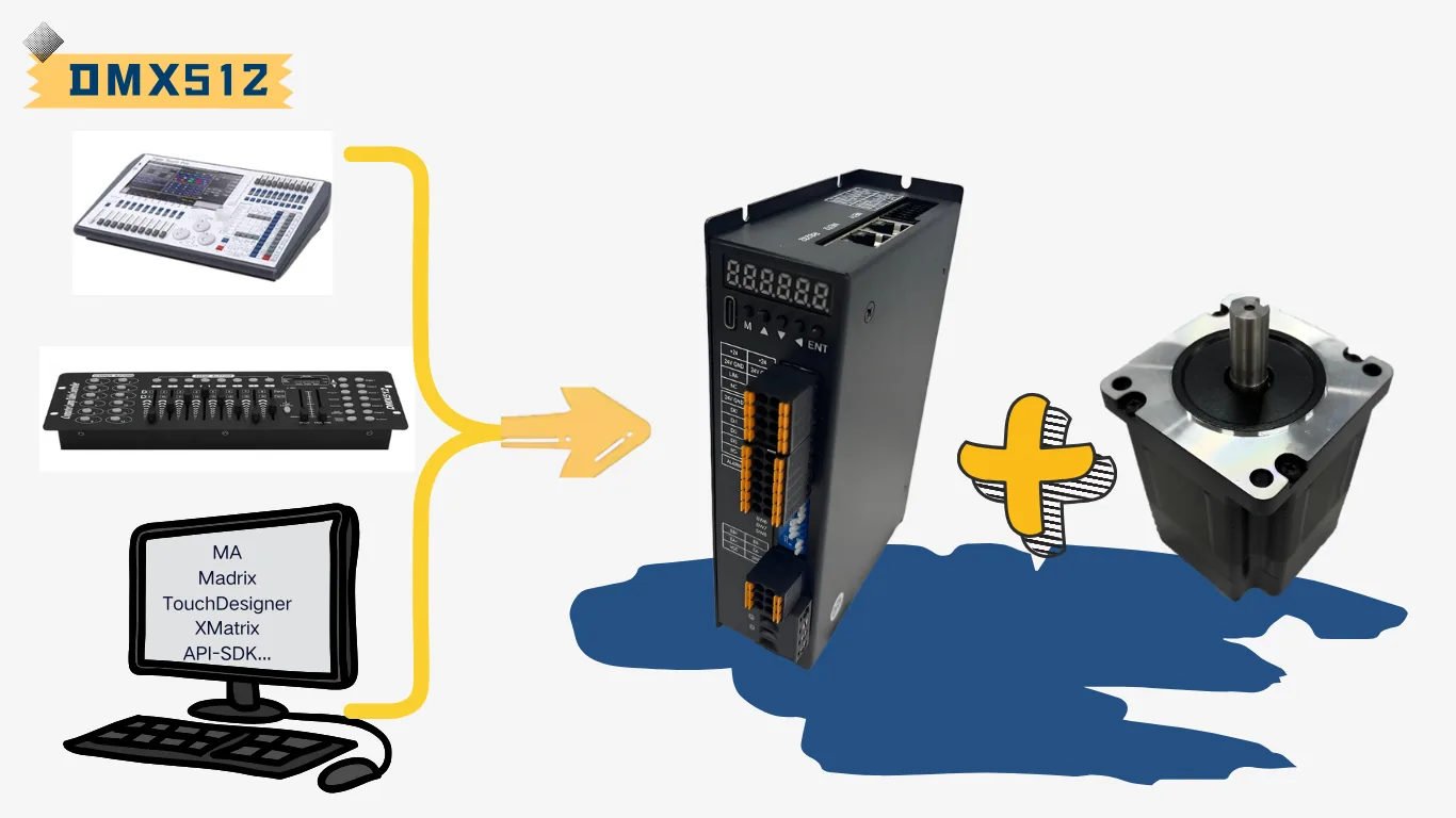
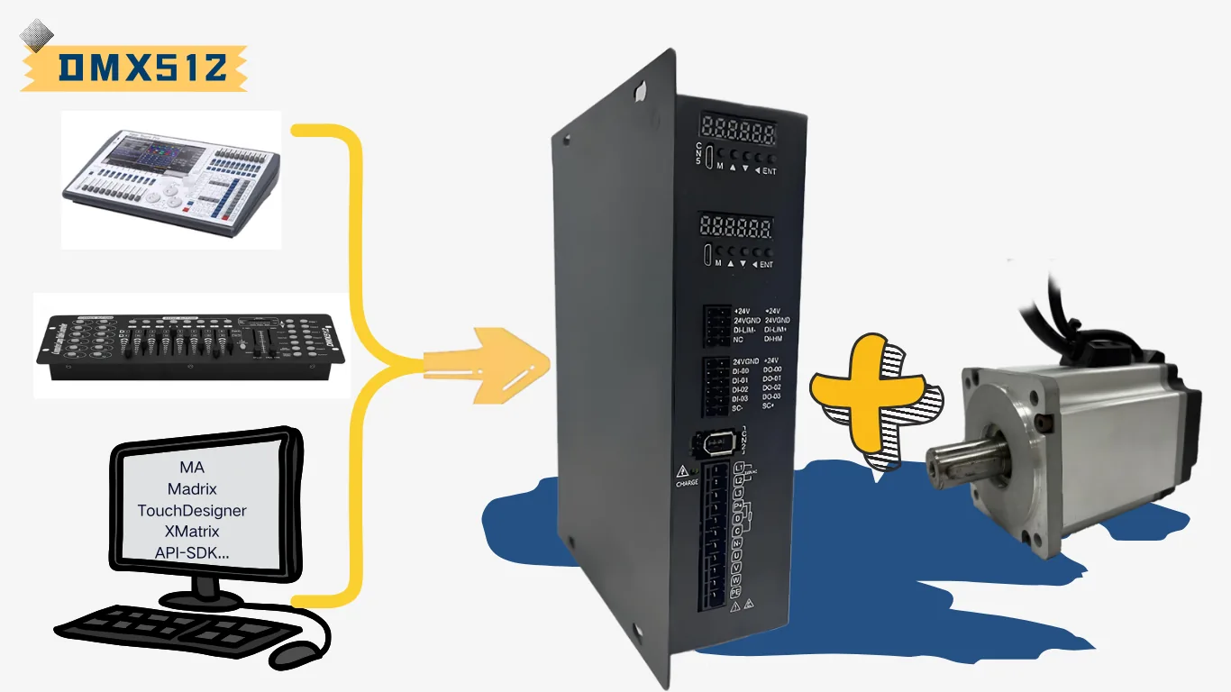
The XMatrix DMX512 Interface moves, programs, and interacts with the motor, and it puts that control into a lighting workflow you already have. A lighting console, a media server, or timeline software can command motor position and speed the way it commands a fixture. The device receives DMX512 directly and turns channel values into homing, positioning, speed, and continuous run. You do not add a PLC, a motion card, or a pulse module.
It addresses the usual problem of putting a motor on a lighting system: poor console fit, a fixed feature set, heavy wiring, an extra controller, and a long commissioning chain. It fits stage machinery, architectural lighting, exhibitions, signage, kinetic matrices, interactive work, and special-purpose machines.
- Channel modes cover position, position + speed, fine position + speed, and continuous forward/reverse.
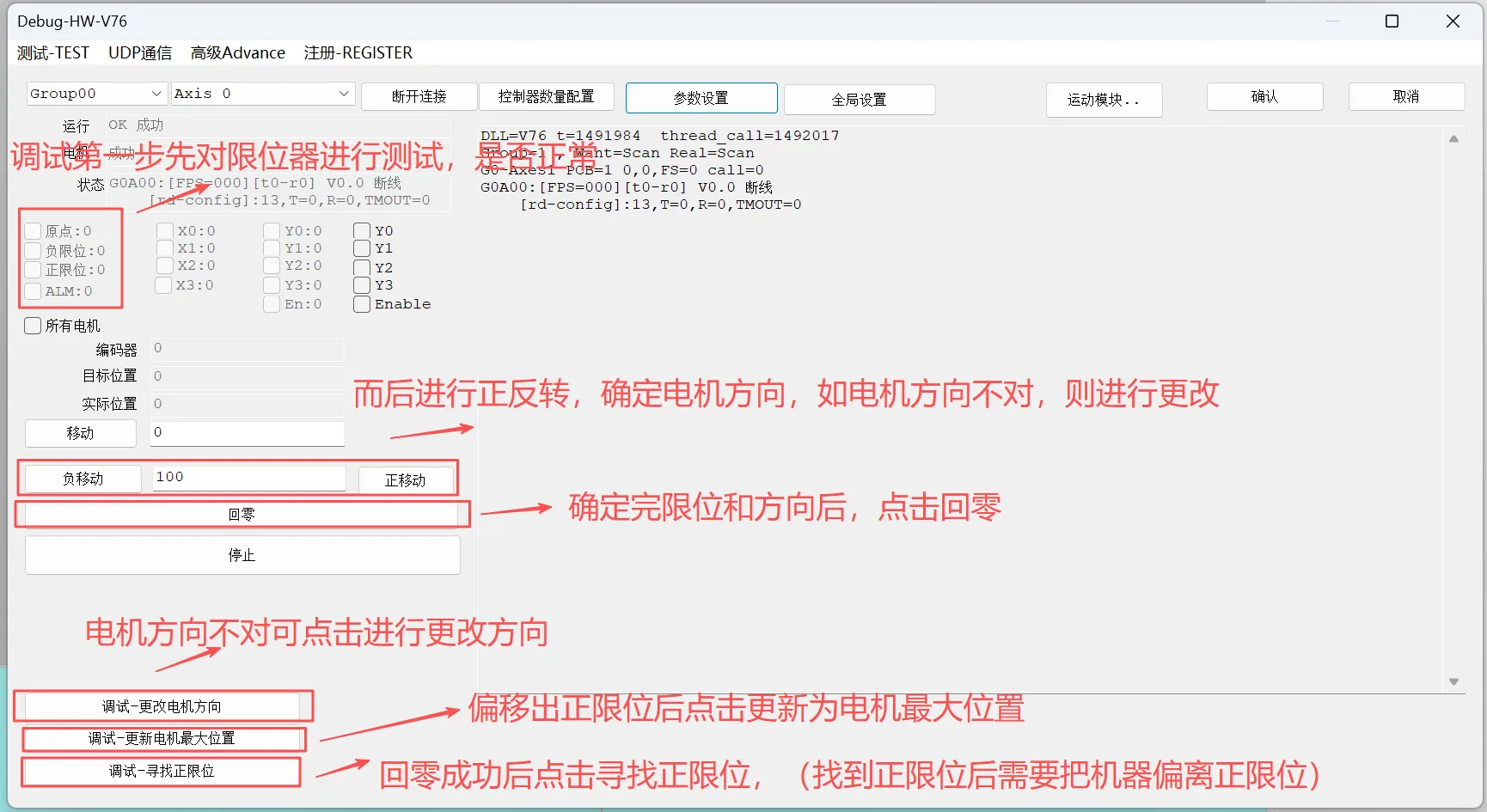
- Set direction, homing, maximum speed, and maximum travel in the commissioning software, then hand the axis to the console.
- Several devices are placed by DMX start address, and they can share a console cue with the fixtures.
- Stepper and servo paths use the same DMX logic and can be mixed on a project.
- Limits, homing, loss-of-signal behavior, brake control, and online firmware maintenance are supported.
Rotating flip-display mechanisms
Flip displays and rotating exhibit boards — many units grouped by channel address, with values combined into a page turn, a wave, or an array change — are one use of the roles and channel modes on this page. Treat each board as a slave and lay out channels by address. A real project is judged from the unit count and the move logic. This page does not expand on it.
Quick start
- Connect power, the motor, home, and the positive and negative limits. Jog and home in the commissioning software first.
- Set motor direction, homing method, maximum speed, and maximum travel. Confirm the mechanism stays inside a safe range.
- Choose a DMX channel mode: P, PV, PPV, or V, and set the slave start address.
- Switch the device to DMX slave mode. Connect DMX+, DMX−, and GND to the console bus in that order.
- Add it on the console as a fixture. The start channel is the software address plus 1. After homing at power-up, move the channel up slowly from a low value.
| Channel modes | How the console drives it | What it fits |
|---|---|---|
| P | Channel 1 is position. 0–255 runs from the start of travel to full travel. | Position from a single fader |
| PV | Channel 1 is position. Channel 2 is move speed. | Position and speed both need to be adjusted on site |
| PPV | Channels 1 and 2 combine into a fine position. Channel 3 is speed. | Long travel, or a finer position resolution |
| V | Channel 1: 0 stop, 1 forward, 2 reverse. Channel 2 is speed. | Continuous run, such as a turntable or a hoist |
Console example: two channels, one motor
Assume software address 0 and channel mode PV. The console starts at channel 1:
- Channel 1: Position. 0 is the start of travel, 255 is the maximum travel set in software, and 128 is about mid-travel.
- Channel 2: Speed. A larger value moves the motor toward the target faster. Maximum speed is still limited by the device parameter.
- First run: Keep both position and speed low. Wait for homing after power-up, then ease the position channel up. If direction or travel is wrong, change it in the commissioning software. Do not drive into a limit from the console.
Detail
The rest of this page follows the usual DMX slave path: wiring, channel map, travel scaling, homing, and loss of signal. A DMX master is a project function and is summarized at the end.
Shared configuration, commissioning, and parameters
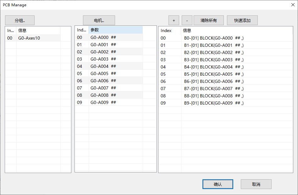
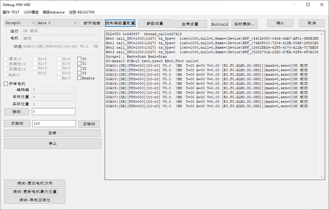
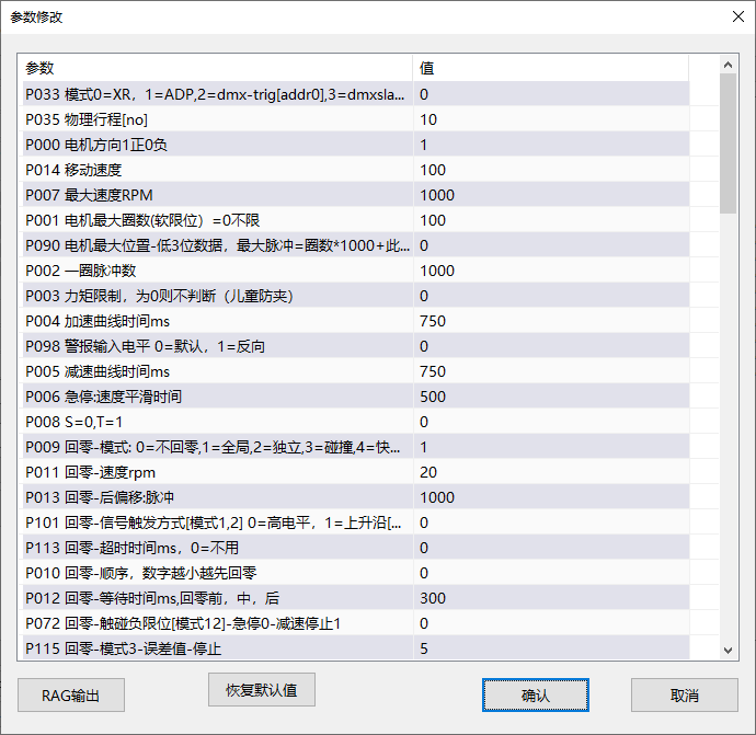
This software function shares the MSP device foundation with the other XMatrix entries. Configure groups, axes, and motion modules, check home, limits, direction, and homing, then set speed, acceleration, travel, and protection. Enter the software mode on this page only after that foundation is done.
Where it sits
The XMatrix DMX512 Interface puts motor motion control and the DMX512 protocol in the same MSP hardware. The console outputs channel values. The device homes, accelerates, scales position, applies limits, and handles errors, so the motor enters a lighting or media control system directly.
- Simpler integration: No extra motion controller. A standard DMX512 signal runs the motor.
- Keep the existing workflow: Address the axis like a fixture. Position and speed go straight into a console cue.
- What you can configure for the site: Open-loop, closed-loop, brake, homing, limits, and loss-of-signal behavior are set for the site.
- Room to extend: P, PV, PPV, and V are the general modes. A non-standard channel map can be defined for a project.
Wiring
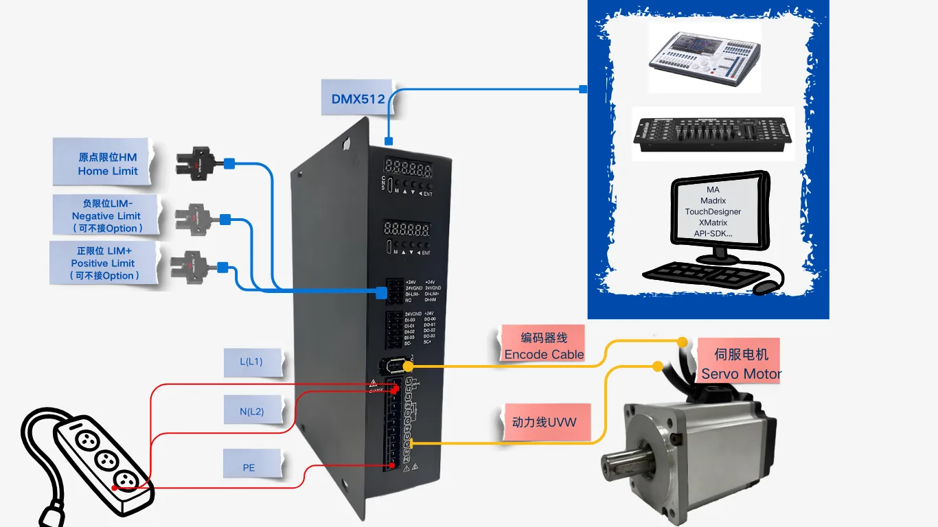
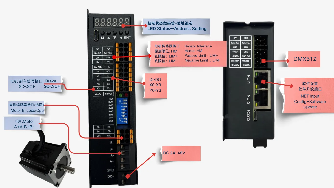
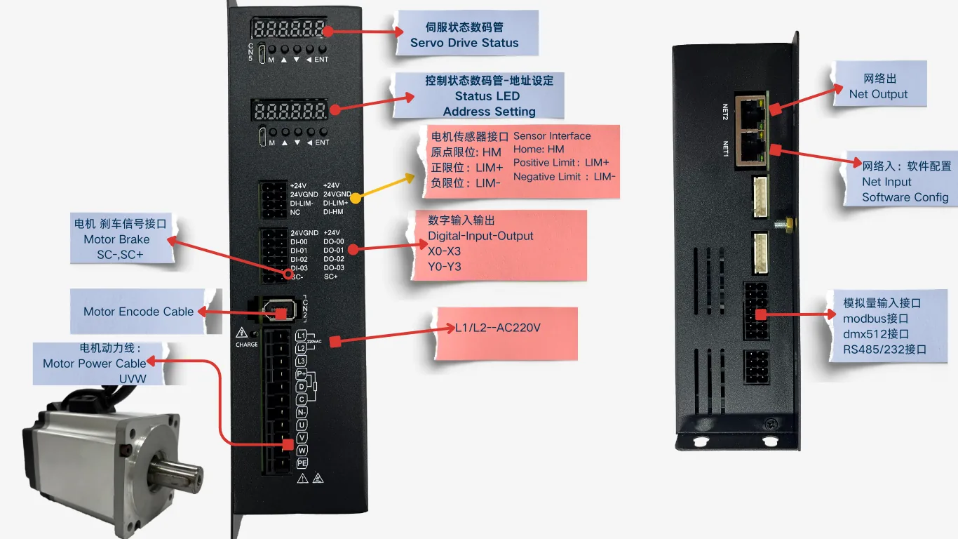
The DMX bus enters the RS485 / DMX port. Supply, power cable, and encoder cable follow the servo path. Limits and home connect to 24 V I/O.
- Connect power and the motor.
- Wire home and the positive and negative limits for the homing method you chose. Home on the first run.
- Connect the console DMX cable to the device RS485/DMX port: RS485+ ↔ DMX+, RS485− ↔ DMX−, GND ↔ DMX GND.
- Several units can daisy-chain over Ethernet for parameters and synchronization. Channel data still comes from the DMX cable.
Slave: follow the console faders
The device is a DMX slave. The console lines the start channel up with the device address, and faders run the motor. This fits lighting, multimedia, and stage-machinery teams who do not want a second host application just for the motors.
- A fader is position, speed, or direction. Coarse position is 8-bit. Fine position is 16-bit.
- Several units are patched by address, the same way fixtures are. Remember: software address starts at 0, console channels start at 1, and console start channel = software address + 1.
- Commissioning order: set direction, travel, and homing in the commissioning software first (leave the mode on software control during commissioning). After that works, switch the mode to DMX slave and hand the axis to the console.
Channel modes: P / PV / PPV / V
Choose the mode under DMX slave mode in the commissioning software. One axis uses 1 to 3 channels. Channels continue from this axis start address.
| Mode | Channels used | Each channel | Fits |
|---|---|---|---|
| P Position | 1 | Position 0–255 | A matrix or a simple lift, where the resolution does not have to be fine |
| PV Position + speed | 2 | Position 0–255 + speed 0–255 | Speed has to be adjusted on site |
| PPV Fine position + speed | 3 | Position high 8 bits + low 8 bits + speed | Long travel, where the position has to land closely |
| V Run mode + speed | 2 | 0 stop / 1 forward / 2 reverse + speed 0–255 | A disc or hoist that keeps turning |
How a fader value becomes travel
Full travel is set in the commissioning software by maximum motor revolutions and the low 3 digits of maximum position:
Full-travel pulses ≈ maximum revolutions × 1000 + low 3 digits
- 8-bit position (P / PV): 0 is the start of travel, 255 is full travel.
- 16-bit position (PP / PPV): 0 is the start, 65535 is full travel, and the values between are proportional.
- Speed byte: 0 is almost no motion, 255 is maximum speed in rpm.
Example: maximum revolutions 10 and low 3 digits 0 give about 10000 pulses of full travel. In P mode, 128 is about halfway. Direction follows the motor-direction setting. Inverting the channel on the console is equivalent.
Power-up, loss of signal, and homing
Power-up
After power-up a slave finds home from the homing parameters, then listens to the console, so the first fader move may wait a few seconds. If homing fails or the servo alarms, the device stays in the error state and no longer follows channels until that is cleared (or until automatic reset after an error is enabled).
Loss-of-signal behavior
“Move to 0 after 5 seconds without a valid DMX frame” is on by default. After about 5 seconds without a valid frame, P / PV / PPV / PP return to travel 0 at homing speed, and V stops. If the site should not return to 0, turn this item off.
Homing triggers
- Home automatically at power-up (set by the homing mode).
- Enable the homing channel and trigger it with that extra channel (default threshold 128).
- A YC-style stage extension holds a function channel in a set range for about 3 seconds (enabled per project).
Matching hardware
On a DMX path the cable is not the only question. A slave and a master need different parts.
| Your role | What to fit | Where it connects |
|---|---|---|
| Slave (follow the console) | DMX cable + terminator; add a DMX converter if the console has only a network port | RS485 / DMX port |
| Slave (home and limits) | Slotted optical sensor ×1 for home + ×2 for limits | Controller HM, LIM+, LIM− |
| Slave (vertical axis) | Brake motor + 24 V relay + brake cable | Controller DO through a relay |
| Online / offline master | DMX master board + DMX cable; offline can also use a trigger button (optional) | RS485 / DMX port, DI |
| Multi-axis daisy chain | Ethernet cable (for parameters and synchronization; channel data still travels on the DMX cable) | Controller Ethernet port |
The full map is in XMatrix Features × MSP Hardware. Accessory categories and models are in Accessories and matching parts.
Common questions
| Symptom | Look here first |
|---|---|
| The fader does nothing | Is the mode slave? DMX wire order and terminator? Is the address beyond the channels the console is sending? Is the unit still homing after power-up? |
| Travel does not line up | Maximum revolutions, 8-bit or 16-bit mode, and whether data invert is on |
| The speed fader does nothing | P / PP have no speed channel. In V mode the first channel must be 0 / 1 / 2. |
| When the signal drops, the axis runs toward 0 | Turn off “move to 0 after 5 seconds with no signal”, or use a YC-style mode (loss of signal only stops) |
| The console has a network port and the device does not respond | Add a DMX converter in between. Do not expect an Ethernet cable to act as DMX. |
| Parameters or the background page will not open | Enter the password the software on site asks for. Request the rule from technical support. |
DMX512 master mode (project function)
Besides a console driving a slave, XMatrix can provide a DMX512 master mode for a project:
- Online master: A PC runs XMatrix in real time. One MSP device turns that run data into a DMX512 bus. Devices further along execute as slaves.
- Offline master: Moves are arranged in advance and written to the master device. The site can run without a PC, from power-up, an input, or a network trigger agreed for the project.
Master output mode, channel count, refresh rate, slave addressing, move capacity, and the trigger method are confirmed from the axis count, the mechanism, and the console on site. They are not applied as if they were the general slave function.