Worm gearboxes
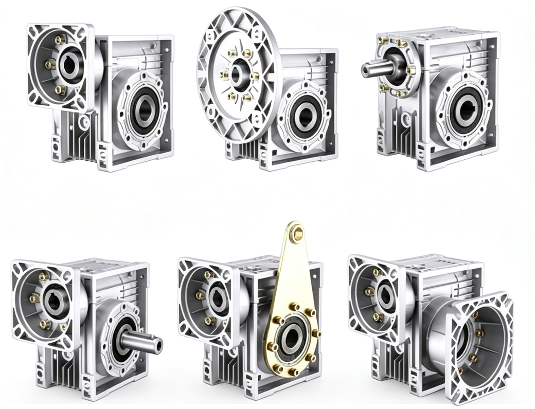
One stage gives a large ratio, and the output turns 90°. The standard frames for 60 / 80 flanges are NMRV040 and NMRV075. Other center distances are configured per project.
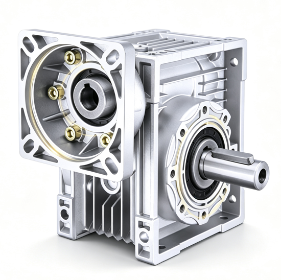
- NMRV04060 / 80 square flange
- NMRV07580 round flange
- 7.5–100Single-stage ratio
- NMRV30Order-code form
Function
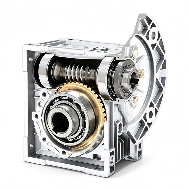
The worm drives the wheel. One stage can reach 1:100. The housing is small, noise is low, and the output turns 90°. At high ratios there is some self-locking tendency, which helps a vertical axis or an axis that should not back-drive after power off.
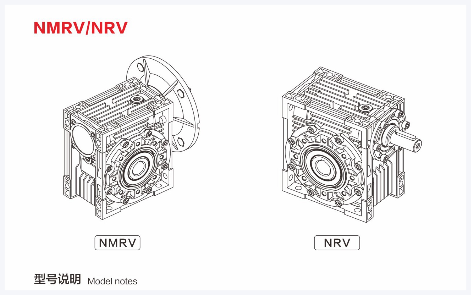
NMRV: flange input. The motor mounts directly on the housing.NRV: input shaft only. You supply the coupling. Standard matching uses NMRV.
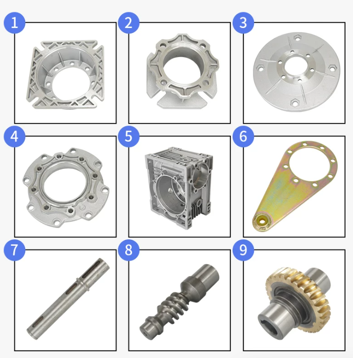
How to choose
- Match the flange. A 60 square flange prefers NMRV040 60×60. An 80 square flange uses 040 at 80×80, or 075 at 80B5 / 80B14.
- Set the ratio. Motor speed ÷ target output speed. Common values are 10 / 20 / 30 / 40 / 50.
- Check output torque. Use the row for the same power and the same ratio. Service factor should be ≥ 1.0.
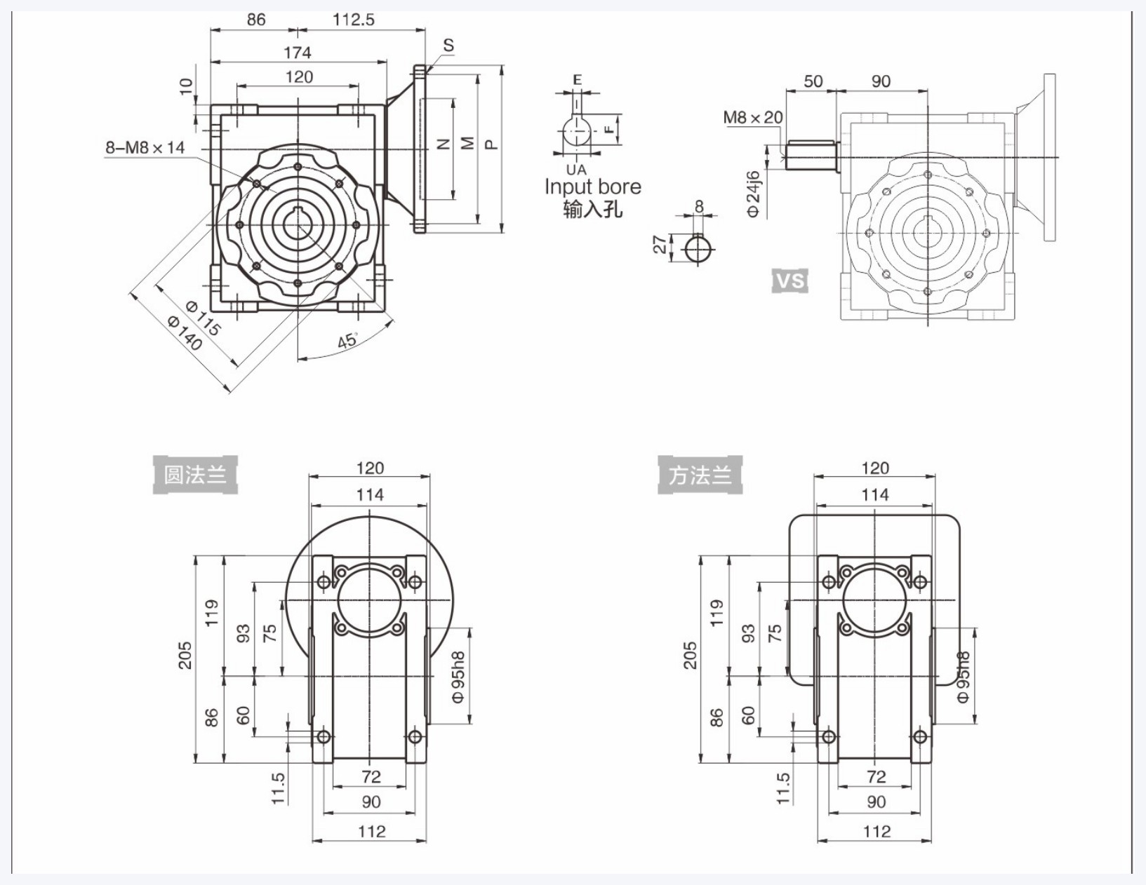
- Check the input bore. The UA bore must equal the motor shaft diameter. If it does not, add a bush. Do not force the fit.
A 60-frame stepper commonly uses a square flange. An 80-frame servo commonly uses 80B5 / 80B14. Write the motor model on the order. Do not send only the center distance.
Standard models
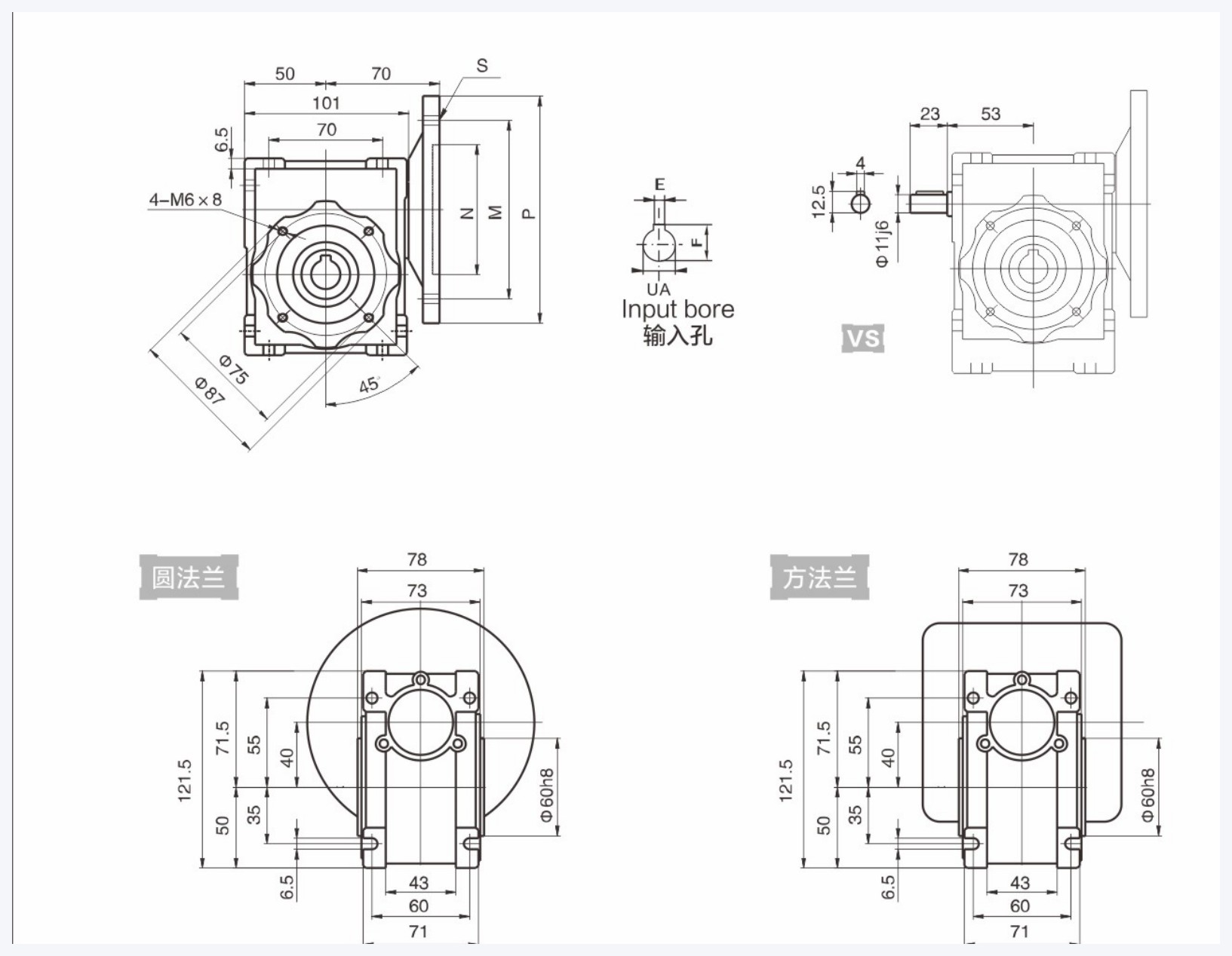
NMRV040 · center distance 40 mm
The light-duty workhorse. Square flanges are available at 60×60 and 80×80, which match 60 / 80 flange motors. Housing mass is about 2.4 kg. Output shaft is Ø25h6.
| Flange | Pilot | Hole pitch | Input bore UA |
|---|---|---|---|
| Square flange 60×60 | 50 | 67 | 9 / 11 / 14 |
| Square flange 80×80 | 60 / 70 / 73 | 94 | 9 / 11 / 14 |
| 71B14 round flange | 70 | 85 | 9 / 11 / 14 |
| 71B5 round flange | 110 | 130 | 9 / 11 / 14 |
NMRV075 · center distance 75 mm
Medium duty. Round flanges include 80B5 / 80B14 and mount directly on an 80-frame servo. Housing mass is about 9 kg. Output shaft is Ø28h6.
| Power | Ratio | Output r/min | Torque N·m | f.s. |
|---|---|---|---|---|
| 0.55 kW | 40 | 35 | 108 | 2.0 |
| 0.75 kW | 25 | 56 | 102 | 2.0 |
| 0.75 kW | 30 | 46.7 | 117 | 2.0 |
| 0.75 kW | 40 | 35 | 147 | 1.5 |
| 1.1 kW | 15 | 93.3 | 95 | 2.1 |
| 1.1 kW | 30 | 46.7 | 171 | 1.3 |
Input is taken at 1400 r/min. Service factor f.s. should be ≥ 1.0. Center distances such as 030, 050, 063, and 090 are configured per project.
Order code
The order code is NMRV plus the ratio, without the flange: NMRV30. Full string example: XR-Online-MSP60-C-2M-NMRV30.
The order must also state the frame (040 / 075), input flange (60×60 / 80×80 / 80B5, and so on), output-shaft direction, and whether an output flange is required. Mass and oil fill follow the documents shipped with the unit.
The 3D model is for mechanism pre-assembly. Pilot and shaft extension follow the dimensions shipped with the unit.
Request NMRV040 3D model Request NMRV075 3D model