Planetary gearboxes
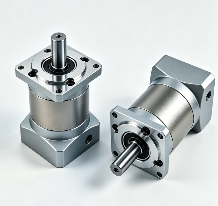
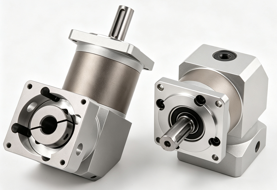
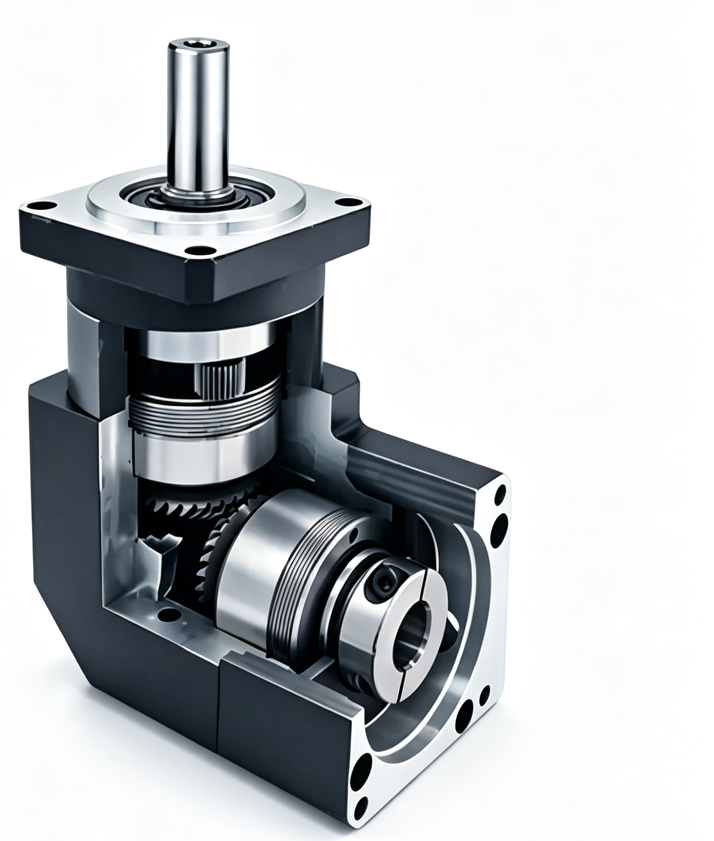
Add a planetary gearbox when motor speed is too high or torque is too low. It reduces speed, raises torque, and improves resolution. Inline series is PF. Right-angle series is ZPF. Flanges cover 60, 80, 110, and 130, in stage 1 (L1) and stage 2 (L2).
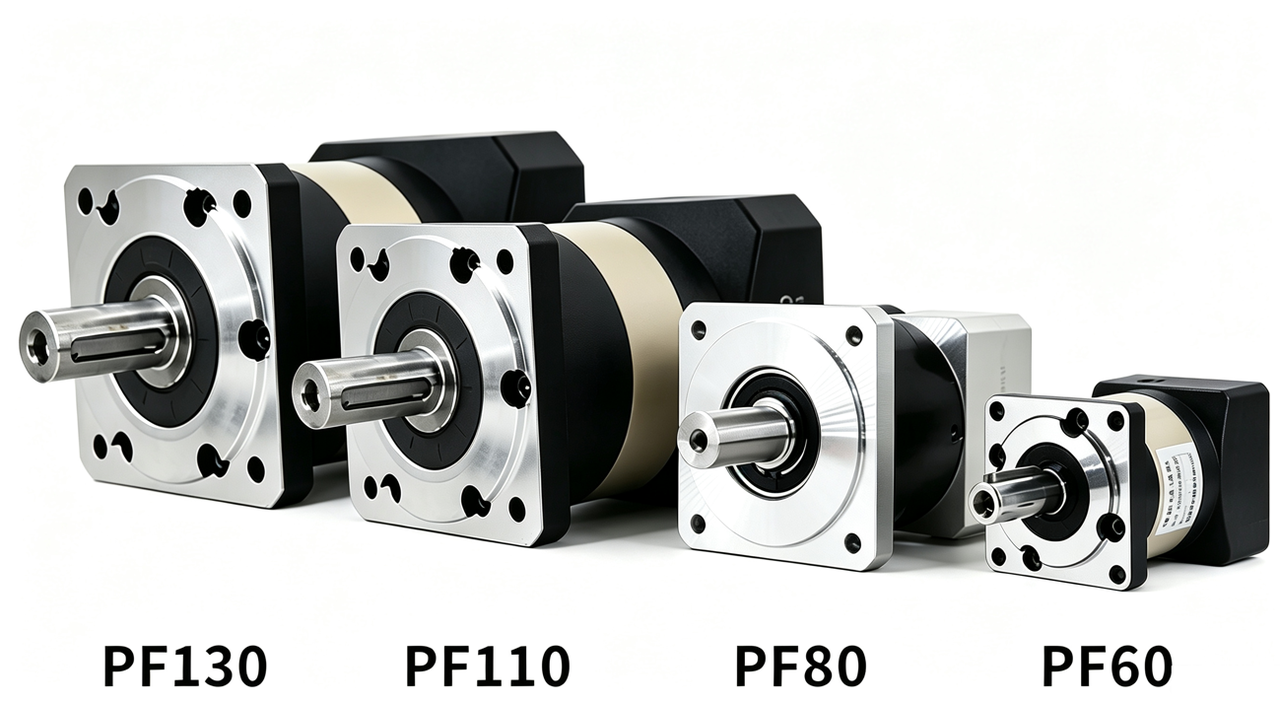
- PF / ZPFInline / right-angle
- 60–130Flange
- L1 / L2Stage 1 / stage 2
- PF10Order-code form
Function
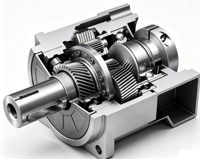
A planetary stage converts motor speed into a slower, higher-torque output. The sun gear is in the center, the planets orbit it, and power leaves through the output flange. Efficiency is high, backlash is small, and stiffness is good, so it suits positioning with an integrated servo drive.
- Not enough torque. Raise rated torque with the ratio instead of moving to a larger motor.
- Speed too high. The mechanism only needs low speed, and direct drive is unstable in that range.
- Resolution too coarse. The same one-revolution command produces a finer output displacement.
- Inertia mismatch. Load inertia is reflected to the motor by the square of the ratio, so acceleration is easier to control.
For a larger ratio, or when the axis should be less likely to back-drive after power off, see the worm gearbox. The order-code segment is NMRV30.
How to choose
- Match the flange first. 400 W / 60 frame uses a 60 flange. 750 W / 80 frame uses an 80 flange. Choose 110 and 130 flanges from the motor pilot.
- Then the direction. Use
PFwhen the motor and load share an axis. UseZPFwhen the output must turn 90°. - Then the number of stages. Ratios 3 / 4 / 5 / 7 / 10 use stage 1 (L1). Ratios of 9 and above use stage 2 (L2). Stage 1 is shorter and more efficient.
- Then check torque. Multiply load torque by 1.5–2 and compare it with the rated table on the model page. Check peak torque at 2 × rated.
In the software, the ratio is applied as revolutions × ratio = actual output revolutions. See XMatrix functions × MSP hardware.
Standard models
The eight 60 / 80 flange models each have a page. 110 / 130 flanges are configured per project. Documents and 3D models are supplied against the motor pilot.
| Model | Form | Matched motor | Ratio | Documents |
|---|---|---|---|---|
PF60L1 | Inline stage 1 | 400W / 60 | 3–10 | PF60L1 |
PF60L2 | Inline stage 2 | 400W / 60 | 9–100 | PF60L2 |
ZPF60L1 | Right-angle stage 1 | 400W / 60 | 3–10 | ZPF60L1 |
ZPF60L2 | Right-angle stage 2 | 400W / 60 | 9–100 | ZPF60L2 |
PF80L1 | Inline stage 1 | 750W / 80 | 3–10 | PF80L1 |
PF80L2 | Inline stage 2 | 750W / 80 | 9–100 | PF80L2 |
ZPF80L1 | Right-angle stage 1 | 750W / 80 | 3–10 | ZPF80L1 |
ZPF80L2 | Right-angle stage 2 | 750W / 80 | 9–100 | ZPF80L2 |
PF110 | Inline | By pilot | Per project | Per project |
PF130 | Inline | By pilot | Per project | Per project |
Nonstandard ratios and other flanges are issued per project. Standard worm frames are on NMRV. Dimension drawings, 3D models, and complete manuals are supplied on request.
Order code
The order code is the series plus the ratio, without the motor flange: PF10, ZPF20. Omit that segment when the ratio is not yet fixed.
| Series | Code segment | Full string example |
|---|---|---|
| PF60 / PF80 / PF110 / PF130 | PF + ratio | XR-Online-MSP400-C-2M-PF10 |
| ZPF60 / ZPF80 | ZPF + ratio | XR-Online-MSP750-C-2M-ZPF20 |
| Worm | NMRV + ratio | XR-Online-MSP60-C-2M-NMRV30 |
Send the motor model, target speed, and load torque so the input hub and order code can be fixed. Frame, cable length, and ratio are selected in the configurator. This page does not assemble a full order code.