Sensors
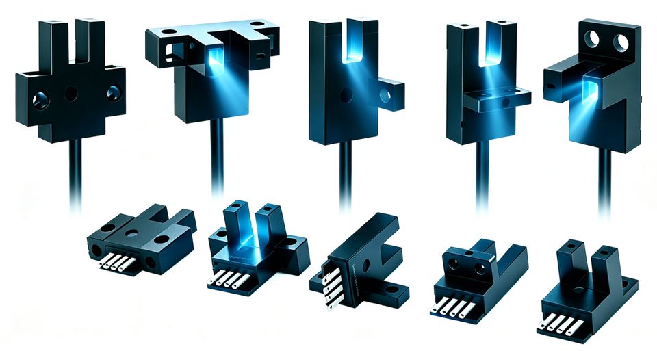
Slotted photoelectric sensors, slot width 5 mm. A vane enters the slot and the output changes state. One for home, two for positive and negative limits.
- Home ×1Homing
- Limits ×2Both ends
- 5 mmSlot width
- NPNDC 5–24 V
Function
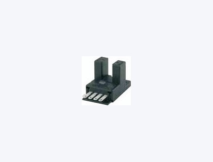
The infrared emitter and receiver sit on the two sides of one U housing. A vane entering the 5 mm slot blocks the beam and the output changes state. Detection does not depend on color, and nothing is mounted on the opposite side. It fits a stage, a nut block, or a home dog.
| Use | Qty | If you leave it out |
|---|---|---|
| Home | 1 | After power-up the absolute position is unknown and the move does not start from the same point |
| Positive and negative limits | 2 | A program error or a failed home can drive into the hard stop |
How to choose
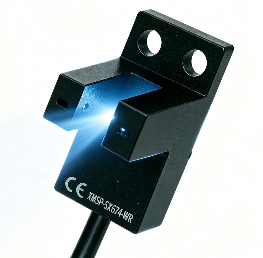
- New bracket: start with SX674-WR, flush mount, 7 mm hole pitch, 1 m cable.
- Existing holes: use the table. Pitch 19: 670 / 671 / 672. Pitch 7: 673 / 674 / 676 / 677. Slot center height 10 mm: 675. Do not rework the holes to force a fit.
- Then the cable exit. 670–674 can be a connector or a cable. 675 / 676 / 677 are cable only.
- Then the logic. Limits usually use dark-ON (black wire). For home, choose black or white from the homing direction. Do not land both wires on the same input.
Standard models
Units are mm.
| Model | Outline | Slot | Hole pitch | Mounting holes | Cable exit |
|---|---|---|---|---|---|
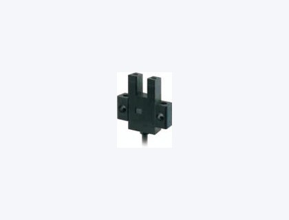
SX670 | Standard L | 5 | 19 | 2-Φ3.2 | Connector / cable |
SX671 | L type | 5 | 19 | 2-Φ3.2 | Connector / cable |
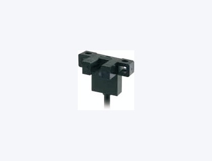
SX672 | T flush, 7 mm | 5 | 19 | Pitch 19 | Connector / cable |
SX673 | Flush mount | 5 | 7 | 2-Φ3.2 | Connector / cable |
SX674-WR | Flush (other orientation) | 5 | 7 | 2-Φ3.5 | Cable 1 m |
SX675 | T flush, 10 mm | 5 | — | Φ3.2 | Cable only |
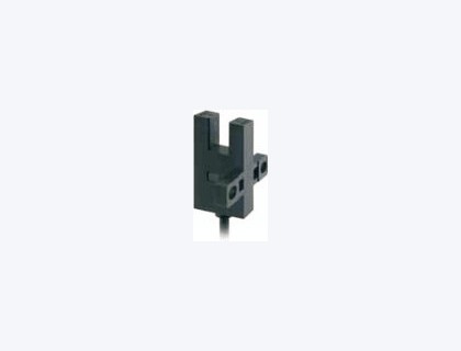
SX676 | F type | 5 | 7 | Φ3.5 | Cable only |
SX677 | R type | 5 | 7 | Φ3.5 | Cable only |
A connector version needs its mating plug. The standard cable is 1 m and can be extended per project.
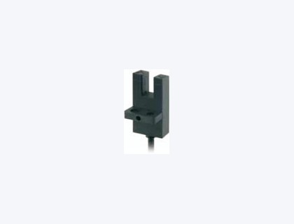
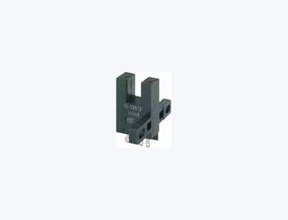
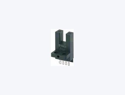
Dimension comparison
Units are mm. Drill from the mounting holes and the pitch.
| Model | Slot | Slot depth | Pitch | Mounting holes | Envelope | Notes |
|---|---|---|---|---|---|---|
SX670 | 5 | 9 | 19 | 2-Φ3.2 | Overall 25.4; mounting-face width 6.95; housing height 13.2 | Standard side mount, chamfer 4-R1 |
SX671 | 5 | 9 | 19 | 2-Φ3.2 | Overall 26.2; mounting-arm height 14.5; side 15.5 | Slot offset from the mounting face |
SX672 | 5 | 9 | 19 | Pitch 19 | Slot center height 7; body height 22.2; T arm 26 | Against the profile side |
SX673 | 5 | 9 | 7 | 2-Φ3.2 | Body 22.2 × 13.4; mounting-face thickness 12.8; optical-axis height 14.4 | Flush, holes Φ3.2 |
SX674-WR | 5 | 9.3 | 7 | 2-Φ3.5 | Reference height 21.5; slot width direction 13.6; side 15.5 | Orientation differs from 673 |
SX675 | 5 | 9 | — | Φ3.2 | Slot center height 10; body height 26.2; T arm 19.5 | Cable only |
SX676 | 5 | 9 | 7 | Φ3.5 | Body 26.2 × 13.4; mounting-face width 13.2 | F type, cable only |
SX677 | 5 | 9 | 7 | Φ3.5 | Body 26.2 × 13.4; mounting-face width 13.2 | R type, mirror of 676 |
670 / 671 housing thickness is about 6.4 mm, slot wall 0.8, slot opening 2. Connector pin pitch is 2.54.
Order code
The usual code is SX674-WR. Home 1 + limits 2, three pieces by default.
| What to state | Example |
|---|---|
| Code | SX674-WR |
| Quantity | Home 1 + limits 2 |
| Cable exit | Cable 1 m; if longer, state the metres |
Other outlines use the model in the table plus a suffix. No suffix, or A, is the connector. -WR is a 1 m cable. 675 / 676 / 677 are cable only.
Documents
Dimension drawings, 3D models, and the complete manual are supplied on request. This page does not offer downloads. Contact us with the model and the documents you need.
Related pages
- SX674-WR — outline and wiring
- XMatrix functions × MSP hardware
- Linear motion
- Accessories