MSP1001 Single-Axis Motion Controller
A direction / pulse interface for a third-party stepper or servo drive, so equipment already in the field can enter the MSP software system.
- AC 110–220VSupply
- 5V · 100 kHzPulse
- Direction / pulseOutput interface
- Several XMatrix functionsMatching software
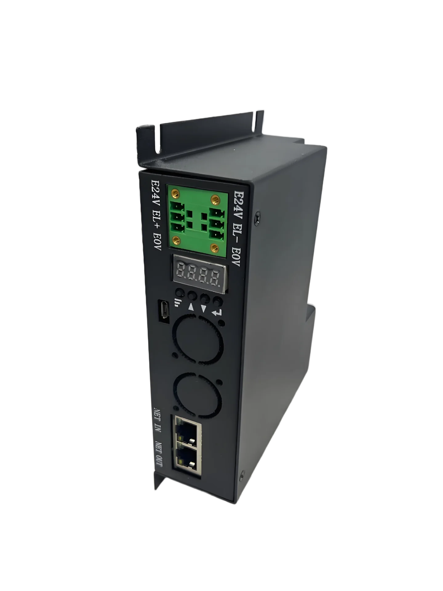
Single-axis connection

Quick check
Fits: A stepper or servo drive is already on site, and its position mode accepts a direction / pulse input that matches MSP1001.
Check before ordering: 5 V signal level, common-anode / common-cathode wiring, direction-and-pulse mode, and whether 100 kHz maximum is enough for the target speed.
One Ethernet daisy chain

Several network groups

Where the interface responsibility stops
MSP1001 does this
Software commands, the position trajectory, direction / pulse output, sensors, and the multi-axis daisy chain.
The third-party drive does this
Motor power, the encoder loop, enable and alarm, gain, stiffness, electronic gearing, and the other drive parameters.
Where it sits
MSP1001 itself has no drive stage. It commands a third-party stepper or servo drive through direction / pulse, so an existing drive can join the same XMatrix software. The order code is written MSP1001, with no open/closed-loop mark O/C and no memory option M.
Ratings
| Item | Description |
|---|---|
| What it connects to | A third-party stepper or servo drive that accepts direction / pulse at a matching level and frequency |
| Supply | AC 110–220V |
| Pulse level | 5V |
| Maximum pulse frequency | 100 kHz |
| Communication | Ethernet daisy chain; DMX512 included |
Wiring and interfaces
Minimum wiring: power + direction/pulse signal cable + Ethernet, with direction and pulse wired to the third-party drive.
Terminal list
The table follows the drawing supplied with the unit. Terminal names match the silkscreen. The source drawing is available on request: MSP1001 signal drawing.
| Group | Terminal / interface | Description |
|---|---|---|
| Power | L / N / FG | AC 110–220V input and protective earth |
| Digital inputs | X0 / X1 / X2 / X3 (with 24V / 0V) | 4 inputs |
| Digital outputs | Y0 / Y1 / Y2 / Y3 | 4 outputs |
| Limits and home | LIM− / LIM+ · HM | Negative limit / positive limit / home |
| Third-party drive interface | PUL+ / PUL− · DIR+ / DIR− · SON · CLR · ALM · PE | Direction / pulse, enable, alarm clear, alarm input, and shield earth |
| Auxiliary supply and analog | E24V / E0V · EL+ / EL− · AI0 / VG | External 24 V, and analog / reference |
| Communication and daisy chain | NET IN / NET OUT · 485 IN / 485 OUT | Ethernet and RS-485 daisy chain |
| Connector designators | J3 · DR15 | Connector designators marked on the official drawing |
Outline and interface drawings
Click an image to view it full size. Engineering drawings are available on request. Dimensions and signals are two separate PDFs.
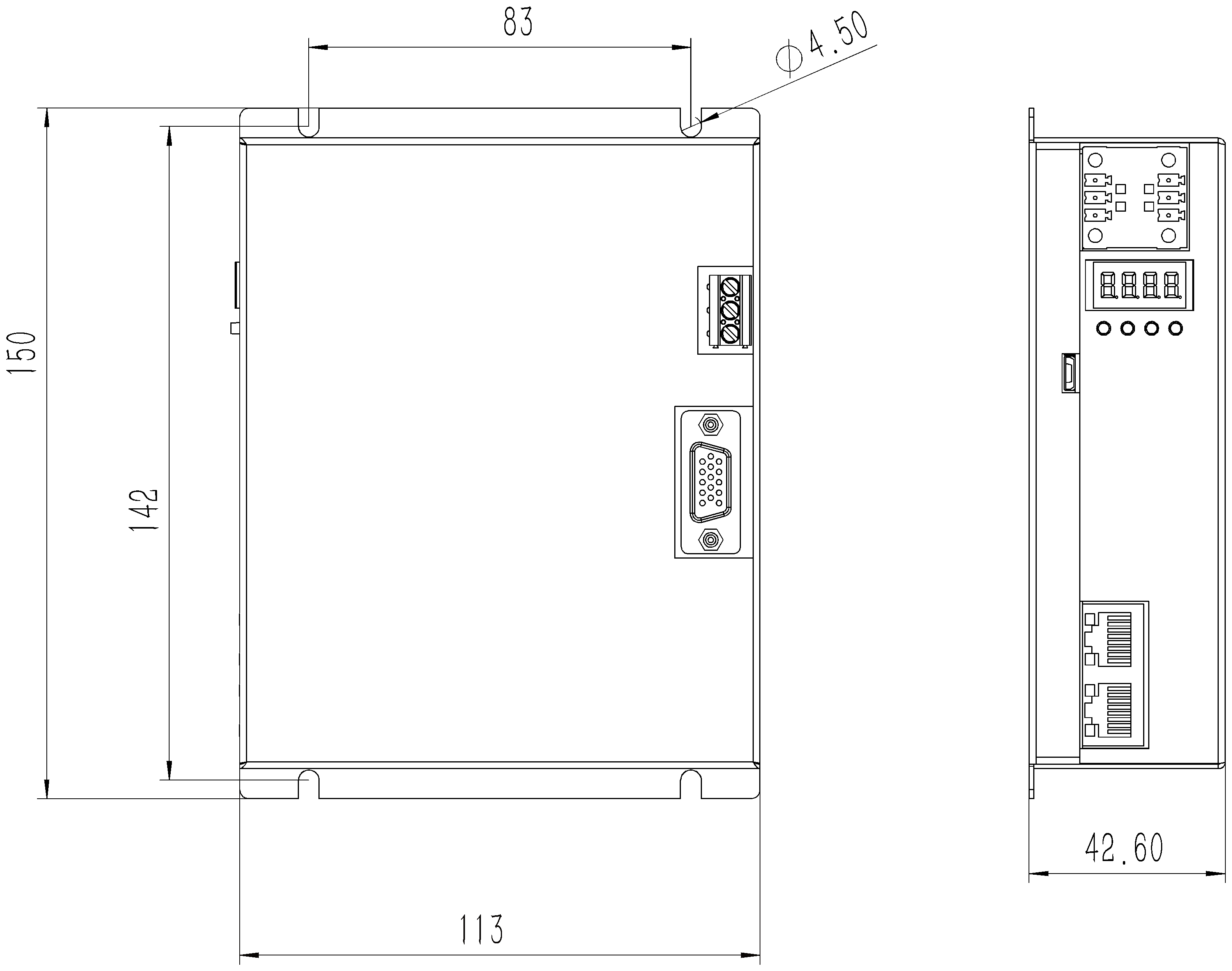
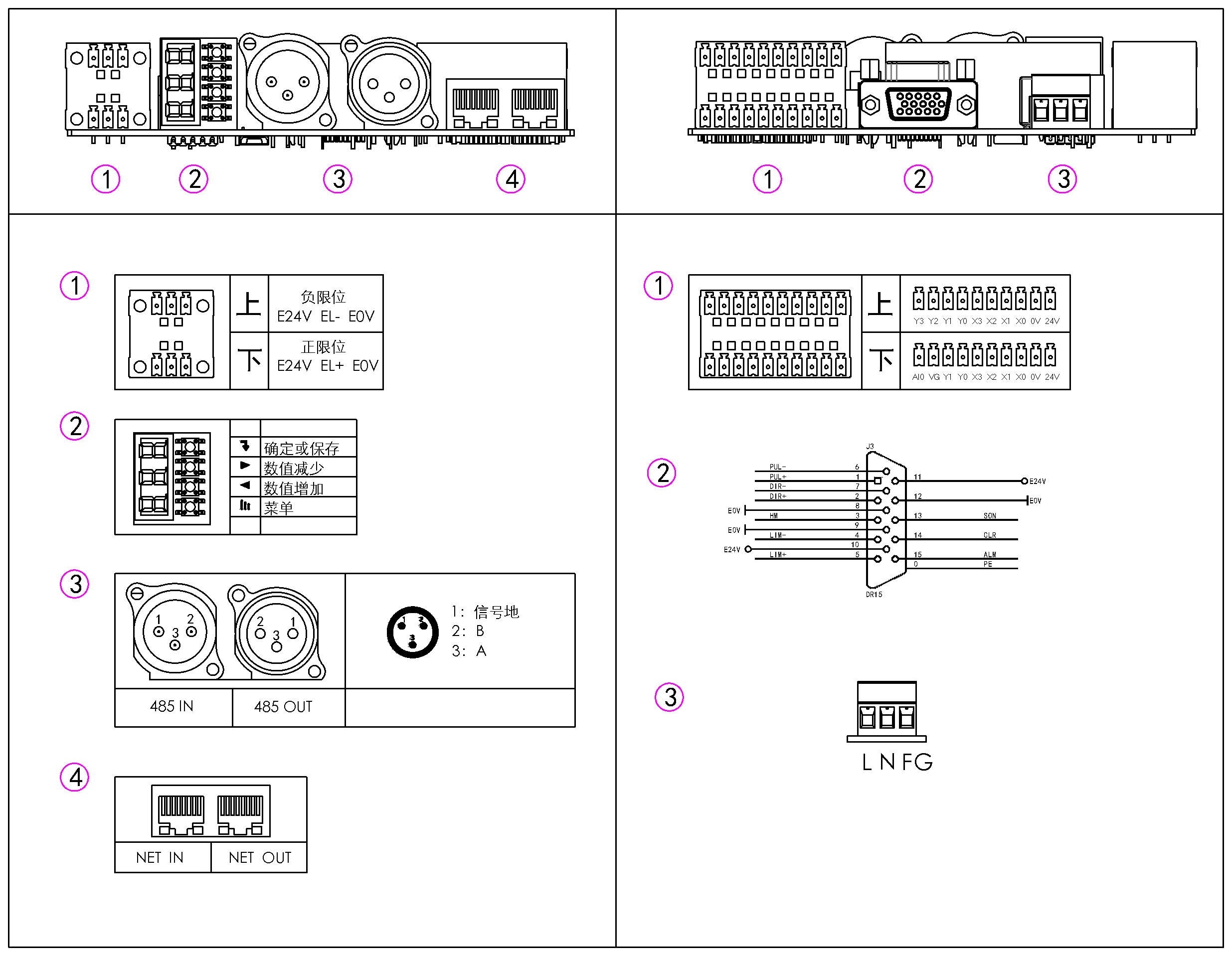
Units are marked on the source drawing. Before connecting a third-party drive, check input level, common-cathode / common-anode, and pulse frequency.
Matching software
The three hardware families share one software interface:
- XMatrix Online — point-and-click moves and sequences
- XMatrix Command Interface — send ASCII commands
- XMatrix DMX512 Interface — a lighting console drives the motor directly (included)
- XMatrix API-SDK / OEM — deeper development, or a version for one industry
Matched motor
The controller itself has no drive stage. It commands a third-party stepper or servo drive through direction / pulse.
- Third-party stepper drive — microstepping and current stay on the drive; the controller only sends direction / pulse.
- Third-party servo drive — the drive runs in position mode; the controller gives the position command as pulses.
- Gain, stiffness, and electronic gearing are set on the drive. The drive must accept pulse + direction, with level and frequency inside 5 V / 100 kHz.
Low-voltage servo and high-power servo layouts have been matched before. MSP1001 does not fix a motor brand or a power step, but the third-party drive still has to be checked item by item: position mode, direction / pulse interface, level, and maximum input frequency.
MSP1001 mounting dimensions and interface drawings are grouped under Documents.
Troubleshooting
| Symptom | Check first |
|---|---|
| No response at power-up | Is the supply AC 110–220V? Are the terminals tight? |
| The drive receives no pulses | Are the direction / pulse wires on the right terminals? Does common-anode / common-cathode match the drive? |
| It moves, but the direction is reversed | Direction-signal polarity, or reverse the motor direction in software |
| Lost steps or stall at high speed | Is the pulse frequency beyond the drive and the motor? Is acceleration too sharp? |
| The host cannot connect | Is the Ethernet link a direct cable or the same subnet? Install WinPcap first. On a daisy chain, do station addresses start at 0? |
First run
- Power the controller (AC 110–220V)
- Connect direction / pulse to the third-party drive
- Plug in Ethernet and connect the host
- Open the selected software and run the first move