Linear motion
Convert rotation into linear travel. A dual-shaft rail guides and carries the load. A belt stage covers long, fast moves. XY, gantry, and screw builds are configured per project.
- Rail / beltTwo standard groups
- ±0.04 mmBelt repeatability
- 40–80Stage profile
- Per projectTravel and holes
Function
The motor output is rotation. For linear travel, either a rail constrains the path, or a belt converts revolutions into millimetres.
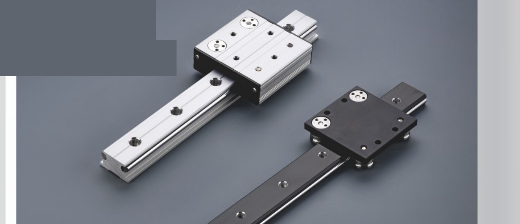
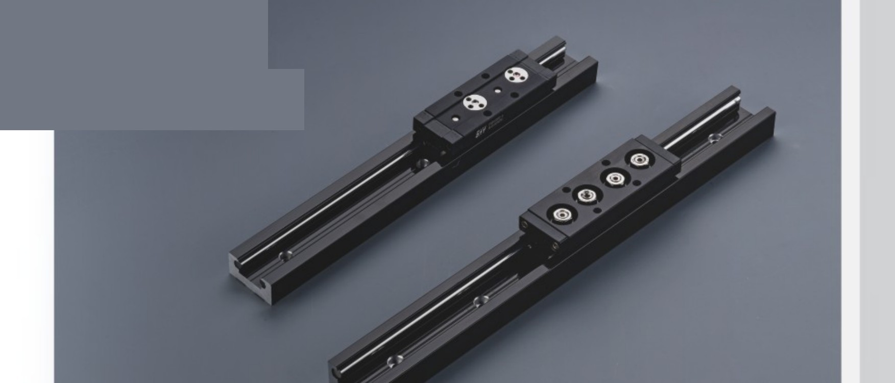
- Dual-shaft rail: two round shafts, carriage held by rollers. No motor. Guidance and load only.
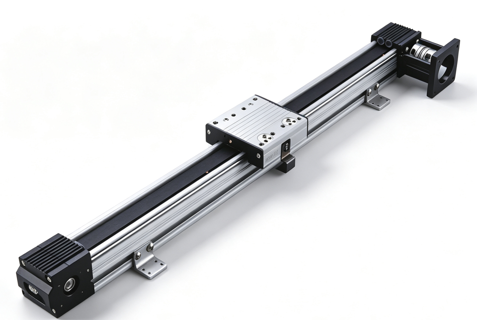
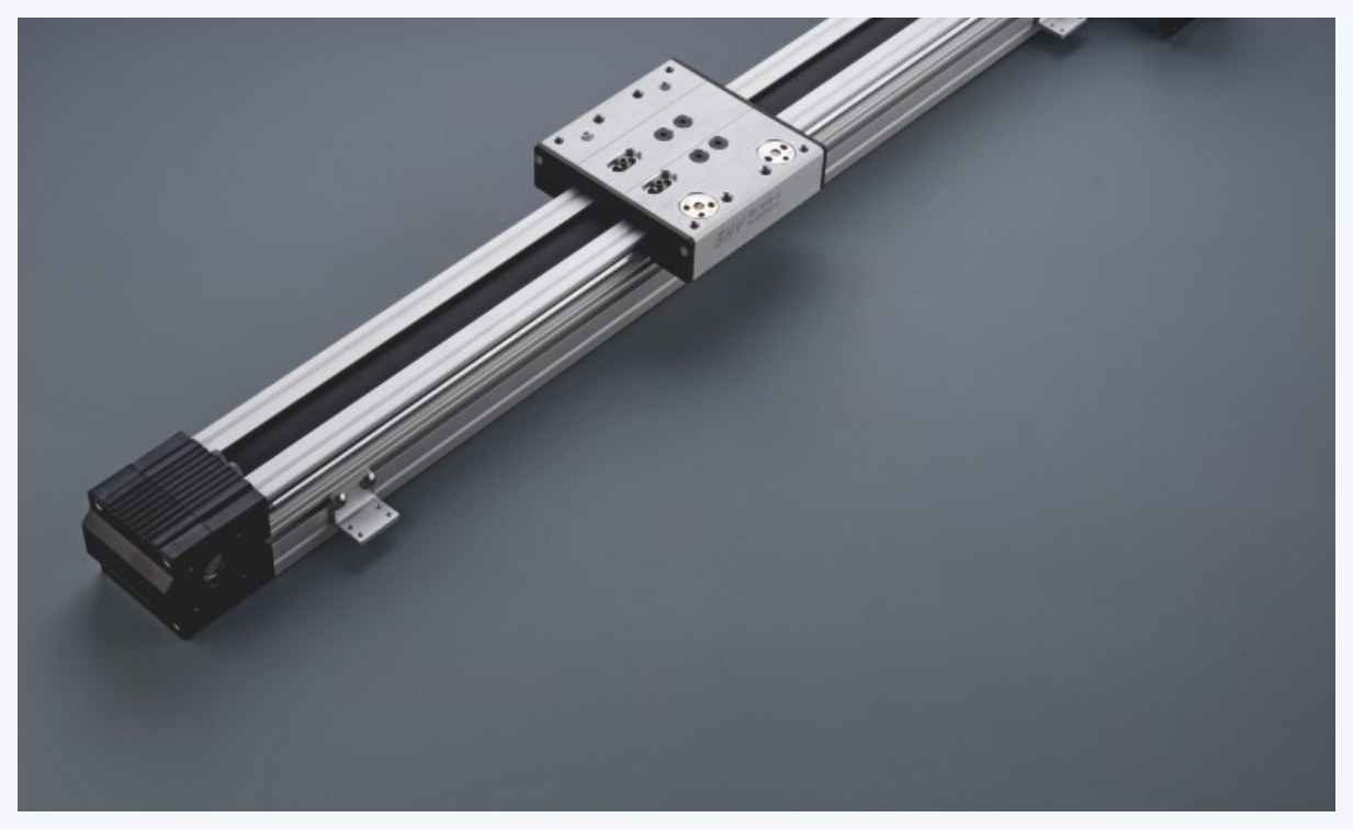
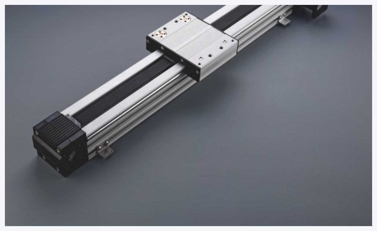
- Belt stage: profile, timing belt, carriage, and motor mount. Travel can be long and speed high. Repeatability grade C is ±0.04 mm.
Use a rail when the slide is pushed by hand. Use a belt stage for powered long travel. For a short stroke and tighter accuracy, a screw can be used and is drawn per project.
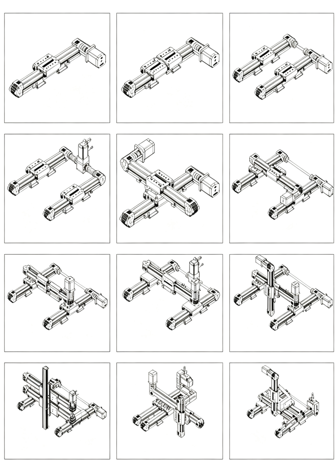
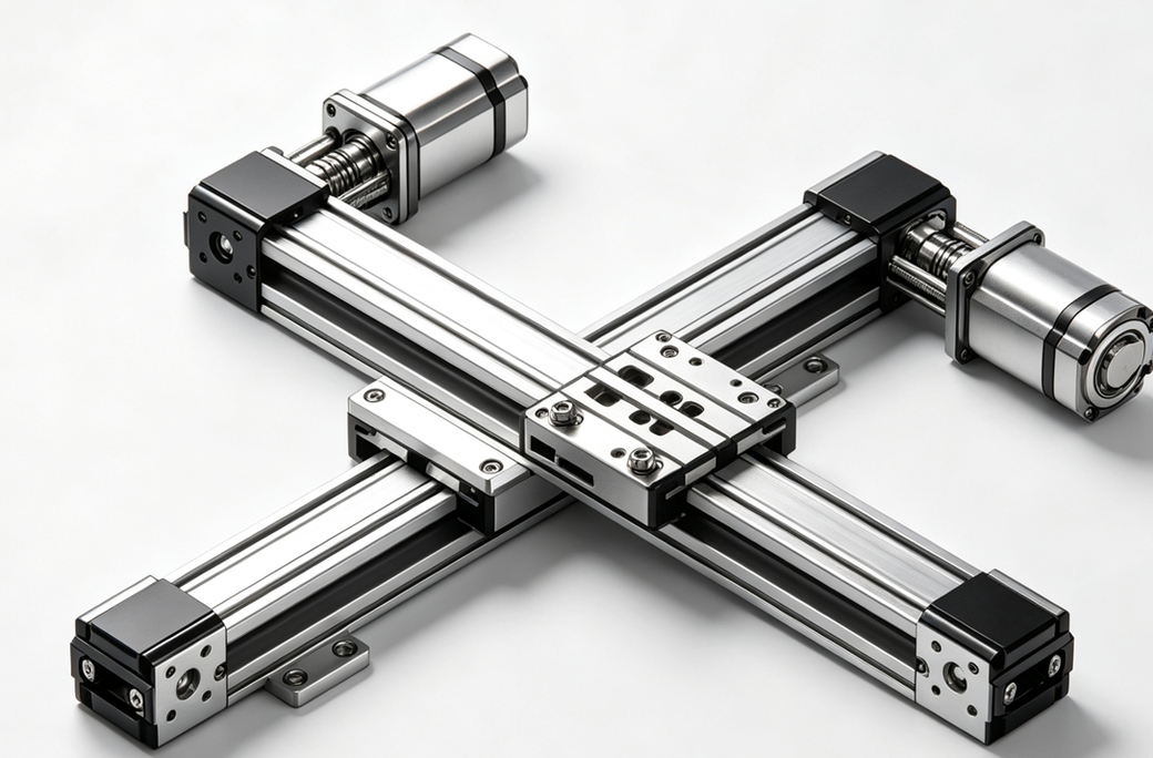
Besides a single-axis stage, the mechanism can be XY, gantry, multi-carriage, or a screw combination. The figure shows the layouts. Travel and connectors are fixed per project.
How to choose
- Does it need a motor? Guidance only: rail. A powered linear axis: belt or screw.
- Set the profile width. Light load and a narrow space start at 40B, then 45, 65 (profile width 60), and 80. A larger section carries more.
- Set the motor position. External BO when the end has mounting depth. Internal BI when the motor mounts underneath or must be hidden.
- Calculate overall length. Overall length = effective travel + end constant. The order must say whether the length is overall or effective.
A belt stage connects directly to the MSP drive. In the software, set the lead as millimetres per revolution. A rail does not change software parameters.
Standard models
Dual-shaft rails
| Series | Construction | Carriage | Width | Use |
|---|---|---|---|---|
OSGG | External | 4 / 6 rollers | 62–148 mm | Guidance, hand push |
ISGG | Internal | 3 / 4 / 5 rollers | 28–100 mm | Side face must stay flush |
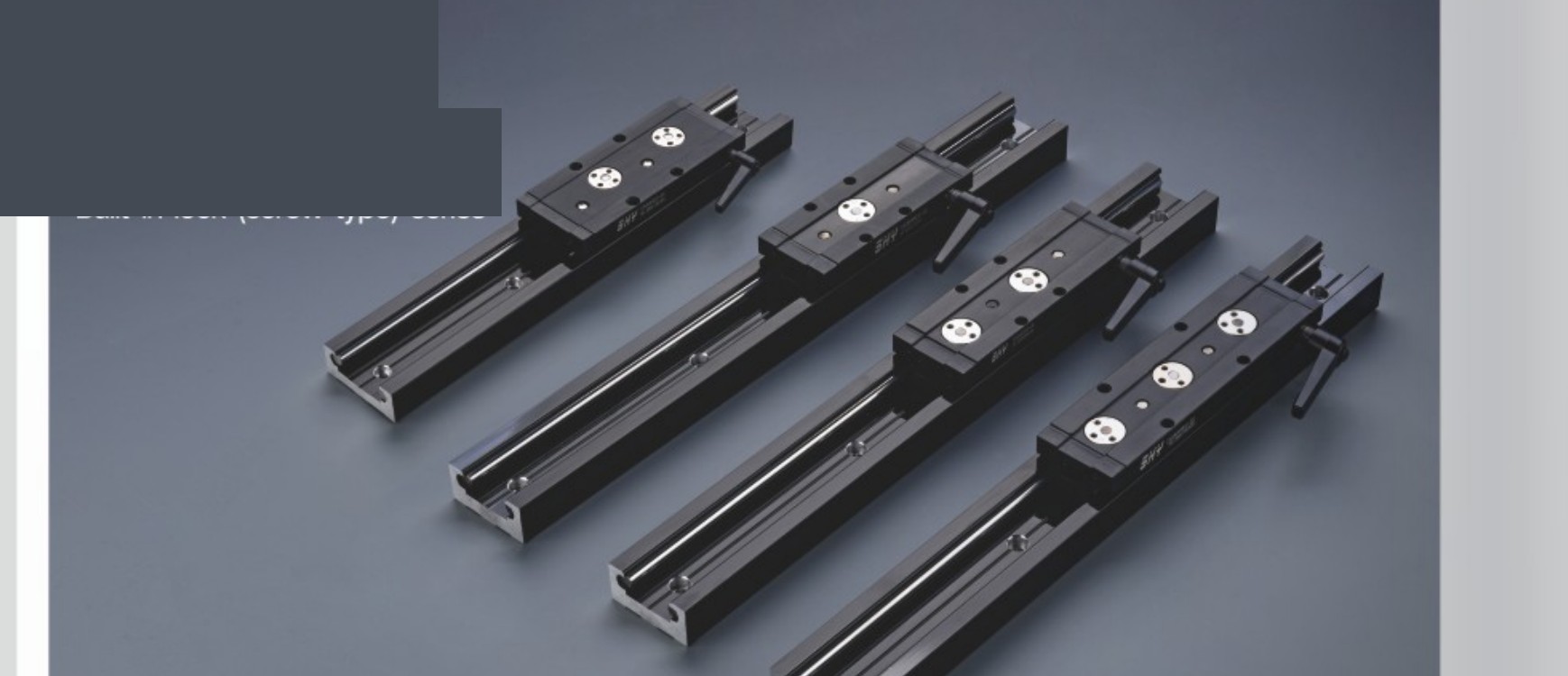
ISGG-LOCK | Internal + lock | Knob / star knob | Same as ISGG | Lock at a stop |
A locking carriage is longer than a plain carriage. Do not copy the plain hole pattern.
Belt stages
| Series | Motor | Profile W×H | Lead | Max mm/s | Overall length |
|---|---|---|---|---|---|
40B | External | 40 × 24 | 75 | 3750 | Travel + 206 / 226 |
45BO | External | 45 × 48 | 75 | 3750 | Travel + 225 / 245 |
45BI | Internal | 45 × 48 | 75 | 3750 | Travel + 239 |
65BO | External | 60 × 31 | 90 | 4500 | Travel + 250 / 270 |
65BI | Internal | 60 × 31 | 96 | 4800 | Travel + 285 |
80BO | External | 80 × 42 | 150 | 7500 | Travel + 284 / 304 |
80BI | Internal | 80 × 42 | 150 | 7500 | Travel + 312 |
Units are mm. The 65 series profile width is 60. Belt grade C is ±0.04 mm. Motors are 100 / 200 / 400 / 750 W. 206 / 226 is short carriage / long carriage.
Order code
Linear units are not in the configurator default cross. The order must state series, effective travel, short or long carriage, motor, shaft direction, and sensor count. Mark the length as overall or effective.
| Item | Example |
|---|---|
| Series | 40B short carriage |
| Travel | Effective travel 800 mm (overall 1006) |
| Motor | MSP400, external |
| Sensors | SX674-WR × 3 |
Do not oil the timing belt. The mounting face should be IT7. A cantilever should not exceed 4 × the body width. XY, gantry, and screw combinations are numbered separately per project.
Documents
Dimension drawings, 3D models, and the complete manual are supplied on request. This page does not offer downloads. Contact us with the model and the documents you need.