MSP Integrated Stepper Drive
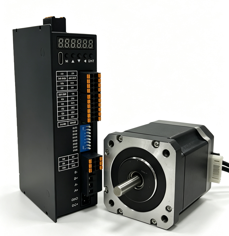
Drive, control, and communication are in one unit. Connect power, the motor, and an Ethernet cable, and the axis can move.
Models: MSP20, MSP28, MSP35, MSP42, MSP57, MSP60, and MSP86.
- DC 24–48VSupply
- 20–86Frame sizes
- Open-loop / closed-loopMode
- Several XMatrix functionsMatching software
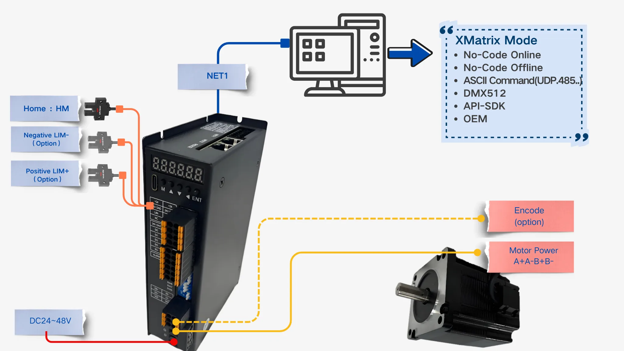
Single-axis connection
Quick check
Fits: A two-phase hybrid stepper in frame 20–86, when software, motion control, and the drive should sit in the same controller.
Confirm: Frame size, rated current, open-loop or closed-loop, brake, and cable length. Above frame 86, or a non-standard drive condition, check MSP1001 first.
One Ethernet daisy chain

Several network groups

Controller interfaces

Where it sits
The MSP integrated stepper drive puts the motion controller, the drive, and protocol handling in one module, and it connects directly to a two-phase hybrid stepper. The usual layout does not add an external PLC, a motion card, or a repeated pulse harness. The hardware segment is written MSPXXX-[O/C]-[SC]-[cable]: XXX is replaced with frame 20, 28, 35, 42, 57, 60, or 86; open-loop is O, closed-loop is C, and a brake option is SC. The full XMSP configuration code also prefixes the selected XMatrix software function.
- Direct connection to a two-phase hybrid stepper, frame sizes 20–86.
- Open-loop or closed-loop. Closed-loop uses an optical encoder and samples position every 50 µs.
- Brake control output (open-collector, external 24 V relay).
Ratings
| Item | Description |
|---|---|
| Matched motor | Two-phase hybrid steppers, frame 20 / 28 / 35 / 42 / 57 / 60 / 86 |
| Operating mode | Open-loop / closed-loop (vector mode, power-angle mode) |
| Supply | DC 24–48V |
| Encoder | Closed-loop: optical encoder, 50 µs position sample |
| Brake | Supported (open-collector output, external relay) |
| IO | 4 in, 4 out |
| Communication | Ethernet daisy chain; DMX512 included |
| Protection | Overcurrent / overvoltage / following-error |
Wiring and interfaces
The minimum system needs three connections: power + motor phases + one Ethernet cable.
Current and I/O
| Item | Description |
|---|---|
| Open-loop current | 1–6 A (set from the frame size and the motor rated current) |
| Closed-loop current | 1–4A |
| IO | 4 in, 4 out |
Microstep DIP
Microstepping is set by DIP switches SW3–SW6. 0 means ON, 1 means OFF:
| Microstep | SW3 | SW4 | SW5 | SW6 |
|---|---|---|---|---|
| Default | 1 | 1 | 1 | 1 |
| 800 | 0 | 1 | 1 | 1 |
| 1600 | 1 | 0 | 1 | 1 |
| 3200 | 0 | 0 | 1 | 1 |
| 6400 | 1 | 1 | 0 | 1 |
| 12800 | 0 | 1 | 0 | 1 |
| 25600 | 1 | 0 | 0 | 1 |
| 51200 | 0 | 0 | 0 | 1 |
| 1000 | 1 | 1 | 1 | 0 |
| 2000 | 0 | 1 | 1 | 0 |
| 4000 | 1 | 0 | 1 | 0 |
| 5000 | 0 | 0 | 1 | 0 |
| 8000 | 1 | 1 | 0 | 0 |
| 10000 | 0 | 1 | 0 | 0 |
| 20000 | 1 | 0 | 0 | 0 |
| 40000 | 0 | 0 | 0 | 0 |
Function DIP
| Switch | Function | Description |
|---|---|---|
| SW1 | Closed-loop mode | 0 = power angle, 1 = vector |
| SW2 | Direction | off=CCW,on=CW |
| SW7 | Command smoothing | on = enabled, off = disabled |
| SW8 | Open / closed loop | off = closed-loop, on = open-loop |
Terminal list
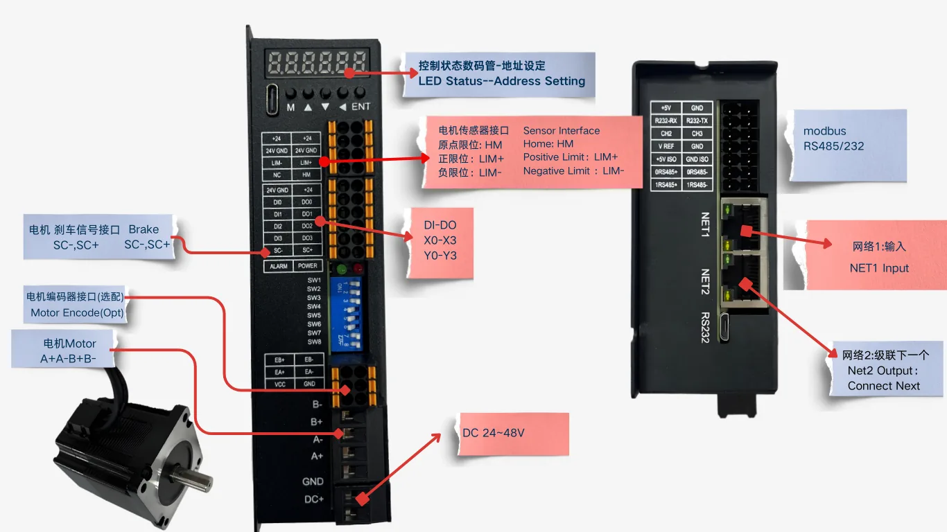
The table follows the drawing supplied with the unit. Terminal names match the silkscreen. The source drawing is available on request: MSP57 interface and dimension drawing.
| Group | Terminal / interface | Description |
|---|---|---|
| Power | DC+ / GND | DC 24–48V input |
| Motor | A+ / A− / B+ / B− | Two-phase stepper phases |
| Encoder (closed-loop) | EA+ / EA− / EB+ / EB− · VCC / GND | Encoder feedback and supply for a closed-loop motor |
| Limits and home | LIM− / LIM+ · HM · NC | Negative limit / positive limit / home; NC is unused |
| Digital inputs | DI0 / DI1 / DI2 / DI3 | 4 inputs (with 24V GND / +24) |
| Digital outputs | DO0 / DO1 / DO2 / DO3 | 4 outputs |
| Switch | SW1 – SW8 | Microstep SW3–SW6; function SW1 / SW2 / SW7 / SW8 (see the two tables above) |
| Communication | RS232-RX / RS232-TX · 0RS485± / 1RS485± · NET1 / NET2 | Serial ports and a dual-Ethernet daisy chain |
| Status lamps | POWER / ALARM | Power lamp and alarm lamp |
| Marks on the drawing | SC− / SC+ · CH2 / CH3 · V REF · +5V ISO / GND ISO | Silkscreen copied from the official drawing. Confirm the use on the project. |
Outline and interface drawings
Click an image to view it full size. Engineering drawings are available on request.
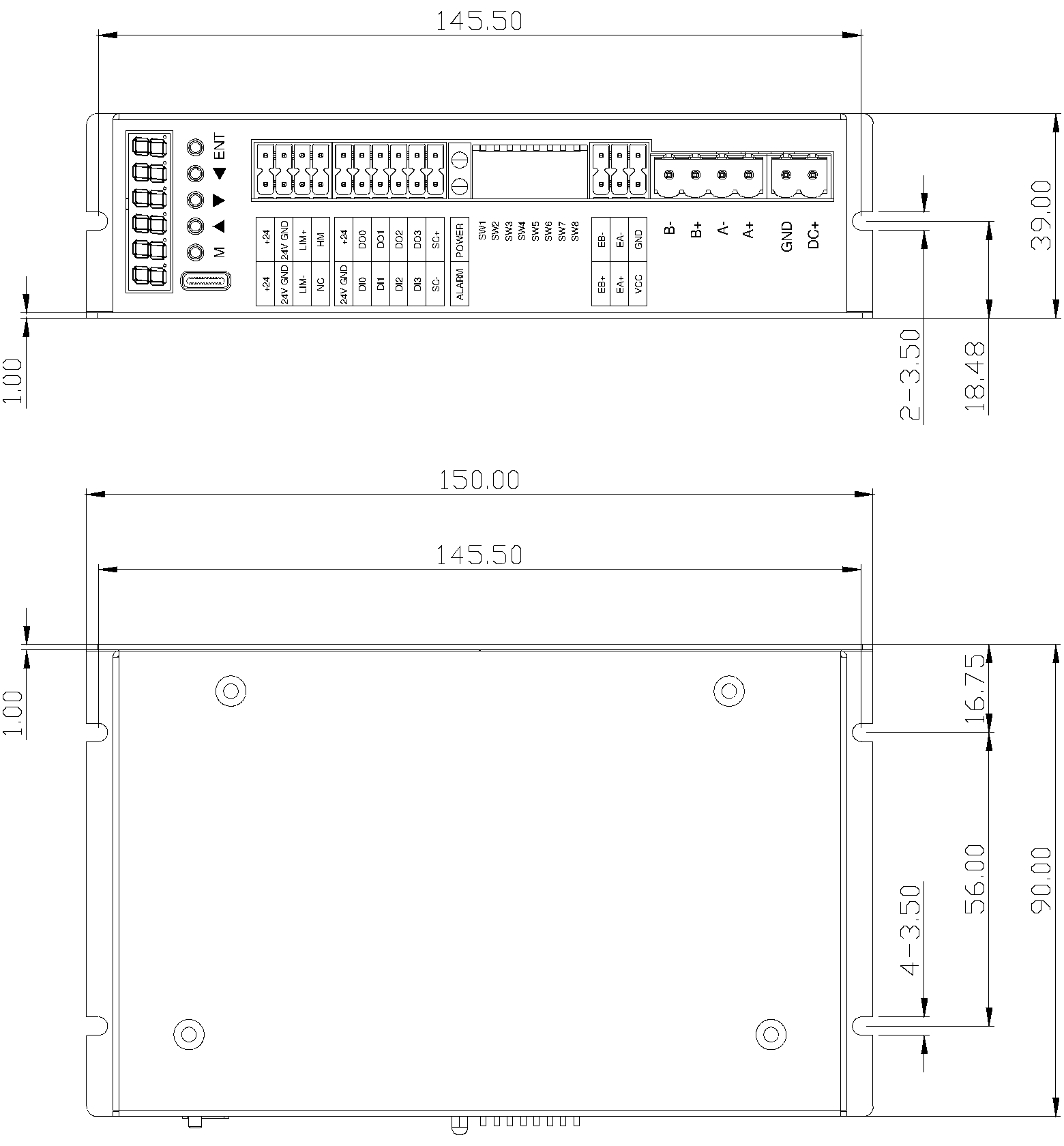
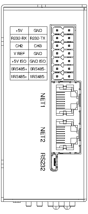
Units are marked on the source drawing. Wire to the terminal silkscreen.
3D models are for mechanical pre-assembly. Contact us for the engineering files.
Matching software
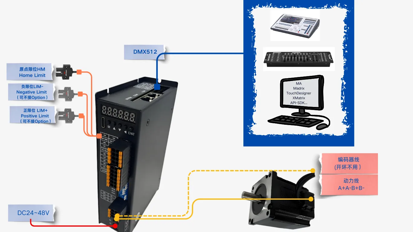
The three hardware families share one software interface:
- XMatrix Online — point-and-click moves and sequences
- XMatrix Command Interface — send ASCII commands
- XMatrix DMX512 Interface — a lighting console drives the motor directly (included)
- XMatrix API-SDK / OEM — deeper development, or a version for one industry
Supported motors
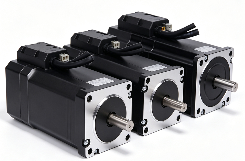
The first table is a quick check by frame size and torque range. The second table lists nameplate values of the ratings published now. The actual motor is confirmed from the MSP rating and the selected version.
| MSP rating | NEMA | Frame torque range | Typical use |
|---|---|---|---|
| MSP20 | NEMA8 | 0.02–0.04 N·m | Smaller frame; the drawing is issued per project |
| MSP28 | NEMA11 | 0.06–0.12 N·m | Smaller frame; the drawing is issued per project |
| MSP35 | NEMA14 | 0.10–0.20 N·m | Smaller frame; the drawing is issued per project |
| MSP42 | NEMA17 | 0.4–0.6 N·m | Light positioning, feeding, small mechanisms |
| MSP57 | NEMA23 | 0.8–3.0 N·m | Labeling, conveying, jog stations |
| MSP60 | NEMA24 | 3.0–3.5 N·m | Medium load, open-close mechanisms |
| MSP86 | NEMA34 | 4.5–12 N·m | Heavy load, multi-station, leadscrew drive |
| MSP rating | Version | Body length mm | Rated current A | Phase resistance Ω | Phase inductance mH | Holding torque N·m | Rotor inertia g·cm² | Shaft diameter |
|---|---|---|---|---|---|---|---|---|
| MSP42 | Standard | 40.0 | 0.8 | 7.5 | 8.1 | 0.4 | 57 | Ø5h6 |
| MSP42 | High torque | 47.5 | 2.5 | 1.25 | 2.5 | 0.48 | 82 | Ø5h6 |
| MSP57 | Standard | 80 max | 5.0 | 0.39 | 1.7 | 2.0 | 480 | Ø8h6 |
| MSP60 | Standard | 105.3 | 5.0 | 0.45 | 2.0 | 3.0 | 690 | Ø8h6 |
| MSP86 | Standard | 100.0 | 6.0 | 0.34 | 2.5 | 4.5 | 1800 | Ø14 |
Phase resistance tolerance ±10%, phase inductance ±20%. The closed-loop version adds an encoder, and body length includes the encoder cover. Shaft diameter h6 is a tolerance zone, not a size.
| Mounting dimensions | MSP42 standard | MSP42 high torque | MSP57 | MSP60 | MSP86 |
|---|---|---|---|---|---|
| Front pilot diameter | Ø22.00h7 | Ø22.00h7 | Ø38.1h7 | Ø36.00h7 | Ø73.00h7 |
| Mounting holes | 4-M3 | 4-M3 | 4-Ø5 | 4-Ø5.00 | 4-Ø6.5 |
| Mounting-hole pitch | 31.00 square | 31.00 square | 47.14 square | 50.00 square | 69.58 square |
| Shaft extension | 24.0±0.5 | 24.0±0.5 | 21±0.5 | 21.0±0.5 | 38.0±0.5 |
Dimension PDFs and 3D models are grouped under stepper motor drawings.
| Order-code step | Matched motor | Supply | Default cable |
|---|---|---|---|
| MSP20 | Frame 20 stepper motor | DC 24–48V | 1 m (options 1 m / 2 m / 3 m / 4 m / 5 m / 8 m / 10 m / 15 m / 20 m) |
| MSP28 | Frame 28 stepper motor | DC 24–48V | 1 m (options 1 m / 2 m / 3 m / 4 m / 5 m / 8 m / 10 m / 15 m / 20 m) |
| MSP35 | Frame 35 stepper motor | DC 24–48V | 1 m (options 1 m / 2 m / 3 m / 4 m / 5 m / 8 m / 10 m / 15 m / 20 m) |
| MSP42 | Frame 42 stepper motor | DC 24–48V | 1 m (options 1 m / 2 m / 3 m / 4 m / 5 m / 8 m / 10 m / 15 m / 20 m) |
| MSP57 | Frame 57 stepper motor | DC 24–48V | 1 m (options 1 m / 2 m / 3 m / 4 m / 5 m / 8 m / 10 m / 15 m / 20 m) |
| MSP60 | Frame 60 stepper motor | DC 24–48V | 1 m (options 1 m / 2 m / 3 m / 4 m / 5 m / 8 m / 10 m / 15 m / 20 m) |
| MSP86 | Frame 86 stepper motor | DC 24–48V | 1 m (options 1 m / 2 m / 3 m / 4 m / 5 m / 8 m / 10 m / 15 m / 20 m) |
Troubleshooting
| Symptom | Check first |
|---|---|
| No response at power-up, lamps off | Is the supply DC 24–48V? Are V+ and GND reversed? Is the supply large enough? |
| Motor does not turn, and it makes noise | Phase order A+ / A− / B+ / B−; does the current setting match the motor rated current? Is microstepping left at Default? |
| Lost steps, position is off | Is acceleration too high? Is the current setting low? For an open-loop axis, consider closed-loop (set SW8 off) |
| The host cannot connect | Is the Ethernet link a direct cable or the same subnet? Install WinPcap first. On a daisy chain, do station addresses start at 0? |
| Connected, but the move does not run | Has the axis been homed? Is a limit active? Is maximum travel 0? Is the device in alarm? |
| Limit or home is not recognized | NPN sensor wiring and supply; is the flag in the slot? Does the signal polarity match the parameter? |
First run
- Connect DC 24–48V
- Connect the stepper phases (A+ / A− / B+ / B−)
- Plug in Ethernet, to the host or to the next unit in the chain
- Open the XMatrix mode or interface you selected (Online / Command / DMX512 …)
- Run the first move and confirm the motor turns