MSP Integrated Servo Drive
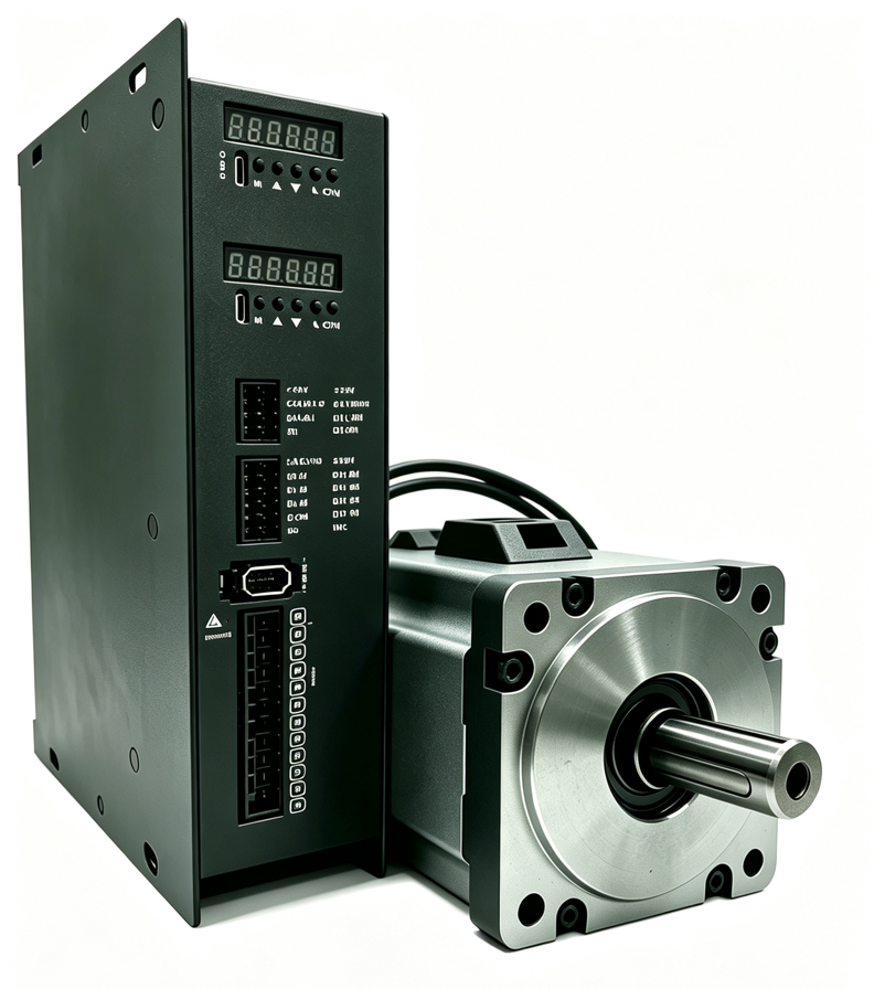
Drive, control, and communication are in one unit. It connects directly to a servo motor up to 1500 W, with incremental or absolute encoder, and a brake option.
Models: MSP100, MSP200, MSP400, MSP750, MSP1000, and MSP1500.
- AC 220VSupply
- ≤1500WPower range
- Incremental / absoluteEncoder
- Several XMatrix functionsMatching software
Single-axis connection
Quick check
Fits: A matched AC servo motor of 100–1500 W, when software, motion control, and the servo drive should sit in the same controller.
Confirm: Power, incremental or absolute encoder, brake, and cable length. A low-voltage servo, a rating above 1500 W, or a non-standard specification: check MSP1001 first.
One Ethernet daisy chain

Several network groups

Controller interfaces

Where it sits
The MSP integrated servo drive puts the motion controller, the drive, and protocol handling in one module, and it connects directly to a servo motor up to 1500 W. The usual layout does not add an external PLC or a motion card. The hardware segment is written MSPXXX-[M]-[SC]-[cable]: XXX is replaced with 100, 200, 400, 750, 1000, or 1500; the absolute-memory option is M, and a brake option is SC. The full XMSP configuration code also prefixes the selected XMatrix software function.
- Incremental or absolute encoder. An absolute encoder does not need homing at power-up.
- Brake control output (open-collector, external 24 V relay).
- 750 W and below can use a more compact body. The software interface is the same.
Ratings
| Item | Description |
|---|---|
| Matched motor | Servo motors up to 1500 W |
| Encoder | Incremental / absolute encoder |
| Supply | AC 220V |
| Brake | Supported |
| Communication | Ethernet daisy chain; DMX512 included |
| Torque limit | Stop on obstruction |
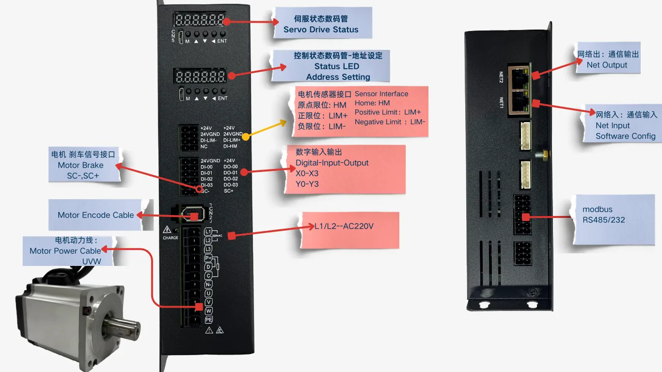
Wiring and interfaces
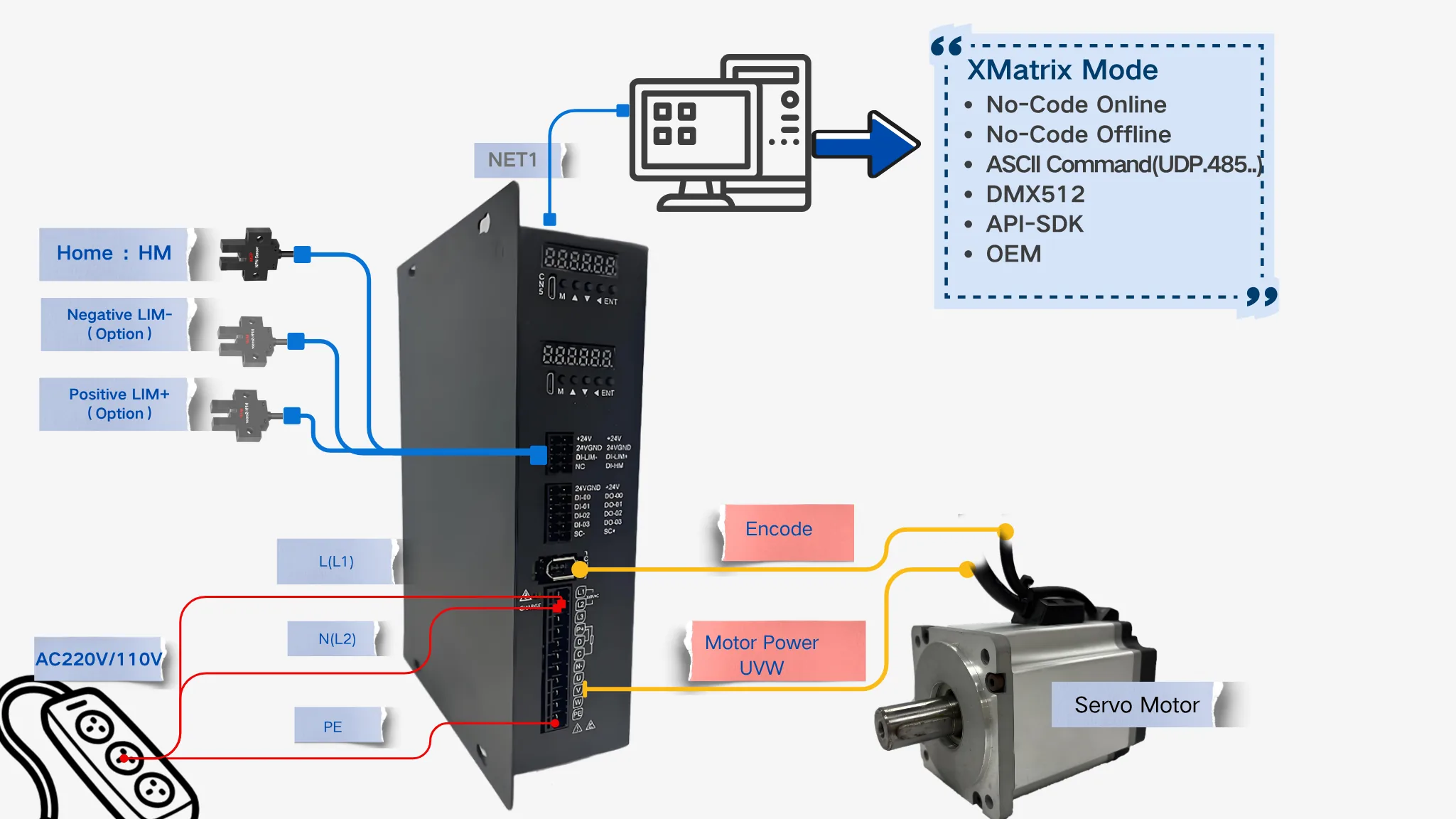
Minimum wiring: power cable (U/V/W) + encoder cable + supply + Ethernet.
I/O and feedback
| Item | Description |
|---|---|
| IO | 4 in, 4 out (on the drive) |
| Feedback | Incremental or absolute, matched to the motor encoder. Encoder ratings are in Supported motors |
Brake and relay wiring
An order code that includes SC means the motor is a 24 V power-off brake: power off locks the shaft so a vertical load does not drop. It is not powered directly by the drive. It must go through a relay.
| Item | Description |
|---|---|
| Brake supply | DC 24 V, separate from the drive power supply |
| How it is controlled | The drive DO output is open-collector, and it cannot drive the brake coil directly |
| Required part | 24 V relay (can be supplied with the unit); add a flyback diode across the coil |
| Wiring order | DO → relay coil; relay contact → 24 V and the brake wires (1 white +24 V / 2 black 0 V) |
| Power-up sequence | Apply power and release the brake before enabling the motor. On power loss the brake sets first. |
Brake parameters and timing are set in software. The mapping is in XMatrix Features × MSP Hardware(item 7, brake output).
Terminal list
The table follows the drawing supplied with the unit. Terminal names match the silkscreen. The source drawing is available on request: MSP750 pinout drawing.
| Group | Terminal / interface | Description |
|---|---|---|
| Power | 220VAC(L / N)· +24V / 24V GND | AC 220V main supply; 24 V is the control supply |
| Digital inputs | DI-00 / DI-01 / DI-02 / DI-03 | 4 inputs |
| Digital outputs | DO-00 / DO-01 / DO-02 / DO-03 | 4 outputs |
| Limits and home | DI-LIM− / DI-LIM+ · DI-HM · NC | Negative limit / positive limit / home; NC is unused |
| Pulse and alarm | PUL+ / PUL− · DIR+ / DIR− · ALM+ / ALM− · CLR+ / CLR− | Differential pairs (pulse, direction, alarm, clear) |
| Encoder / feedback | 0A / 0B / 1A / 1B · G_A · G_5V / +5V · 5V_E / G_E · U_TX / U_RX · AI0 | Incremental / absolute feedback and the upstream interface |
| Communication and daisy chain | NET1 / NET2 | Dual Ethernet ports, daisy-chained |
| Status lamps | CHARGE | DC-bus charge lamp |
| Marks on the drawing | SC− / SC+ · TIM5 / TIM3 | Silkscreen copied from the official drawing. Confirm the use on the project. |
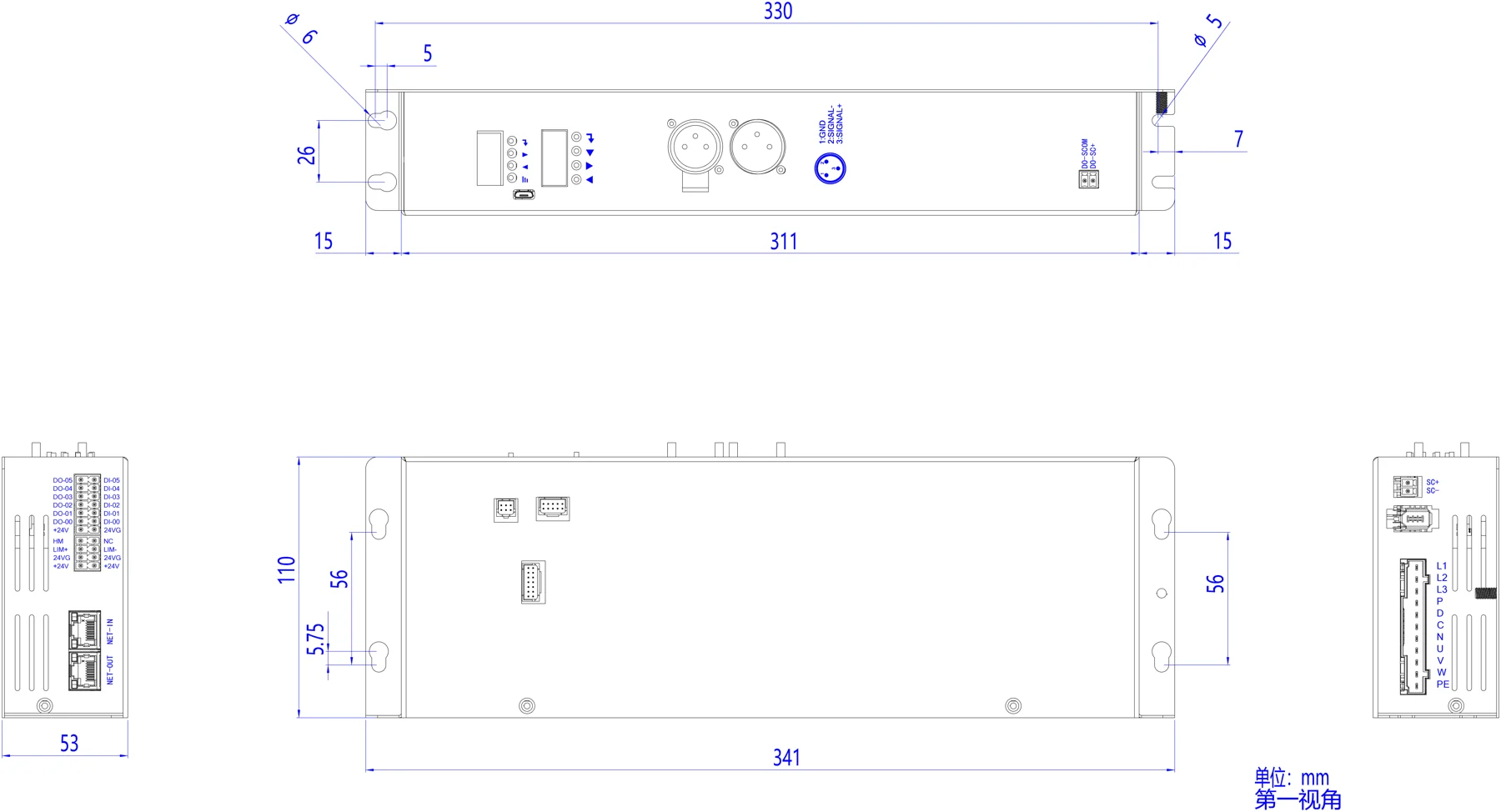
Outline and interface drawings
Click an image to view it full size. Engineering drawings are available on request.
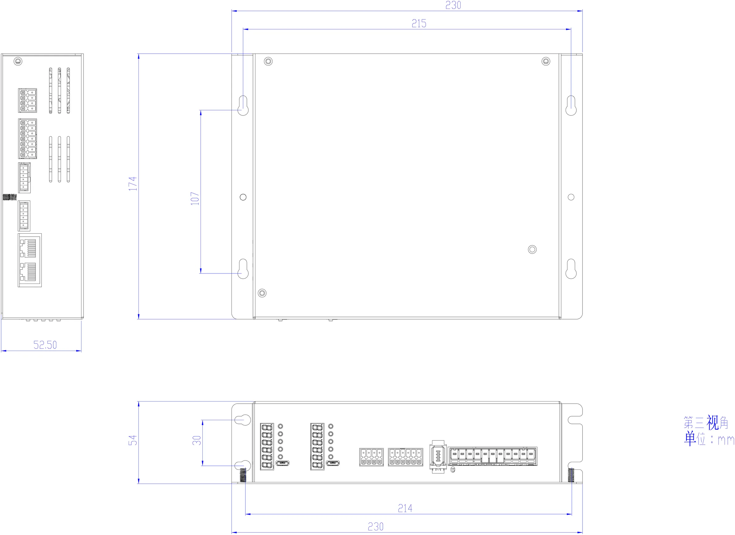
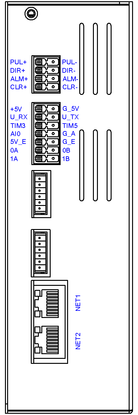
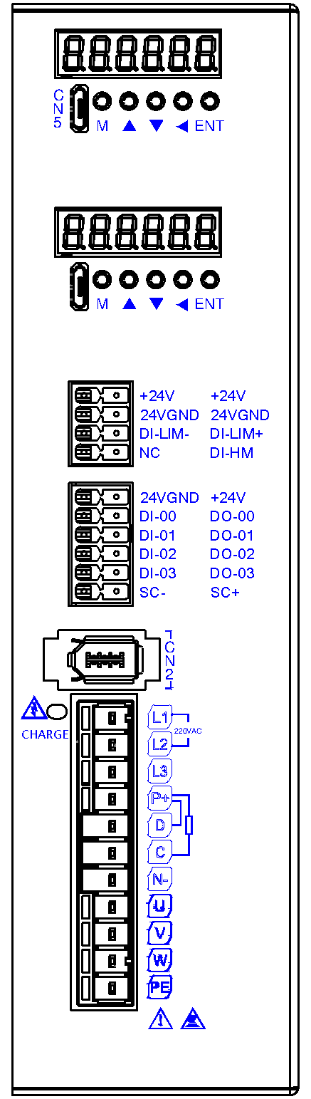
Units are marked on the source drawing. Wire to the terminal silkscreen.
3D models are for mechanical pre-assembly. Contact us for the engineering files.
Additional outline
The integrated servo drive is one hardware unit. Below are additional outline and wiring notes for the same unit. Configurator order codes are still written by power step (MSP100 / MSP400 / MSP750).
Matching software
The three hardware families share one software interface:
- XMatrix Online — point-and-click moves and sequences
- XMatrix Command Interface — send ASCII commands
- XMatrix DMX512 Interface — a lighting console drives the motor directly (included)
- XMatrix API-SDK / OEM — deeper development, or a version for one industry
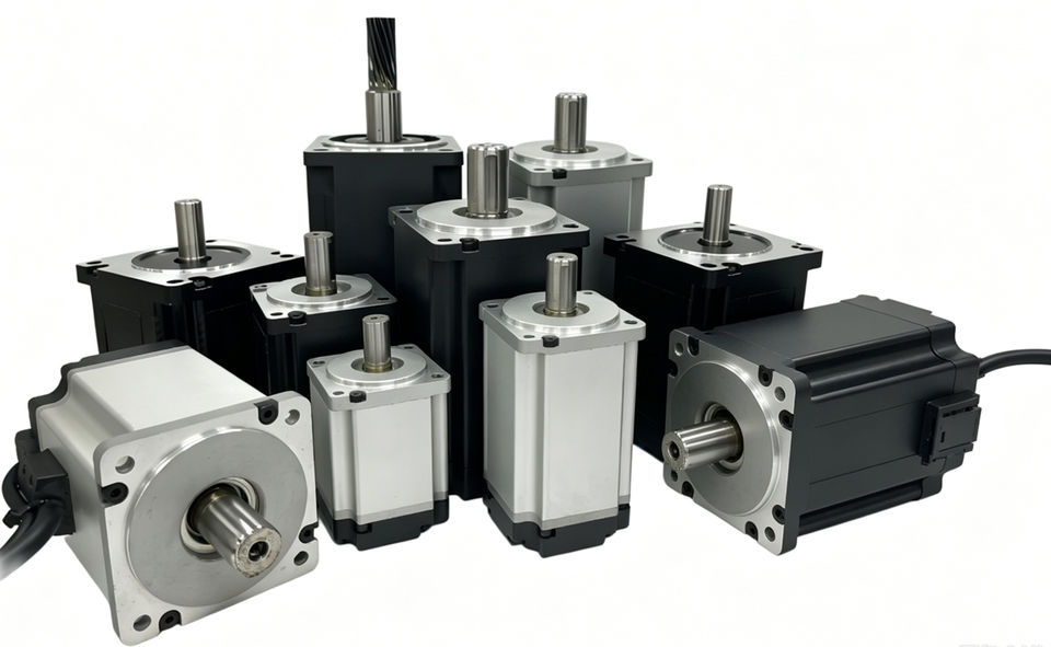
Supported motors
Performance table
| MSP rating | Frame | Power W | Rated N·m | Peak N·m | Rated A | Inertia ×10⁻⁴ kg·m² | Speed r/min | Mass kg |
|---|---|---|---|---|---|---|---|---|
| MSP100 | 40 | 100 | 0.32 | 1.11 | 0.96 | 0.073 | 3000 / 6000 | 0.50 |
| MSP200 | 60 | 200 | 0.64 | 1.9 | 1.1 | 0.3 | 3000 / 6000 | 1.00 |
| MSP400 | 60 | 400 | 1.27 | 3.82 | 2.6 | 0.5 | 3000 / 6000 | 1.20 |
| MSP750 | 80 | 750 | 2.39 | 7.1 | 4.5 | 1.5 | 3000 / 6000 | 2.20 |
| MSP1000 | 80 | 1000 | 3.2 | 6.4 | 4.6 | 2.1 | 3000 / 5200 | 2.64 |
| MSP1500 | 130 | 1500 | 4.8 | 14.4 | 6 | 7.2 | 3000 / 4000 | 4.80 |
Mounting table
| MSP rating | L mm | Brake L mm | Flange | Pilot | PCD / mounting holes | Shaft diameter × extension | Key / shaft end |
|---|---|---|---|---|---|---|---|
| MSP100 | 76.9 | 104.6 | 40 | Ø30 | Ø46 · 2-Ø4.5 | φ8 × 21.5 | Key length 15.5 · M3 |
| MSP200 | 81 | 116 | 60 | Ø50 | Ø70 · 4-Ø5.5 | Ø14 × 30±0.5 | Key 5 × 25 · M5×12 |
| MSP400 | 93 | 128 | 60 | Ø50 | Ø70 · 4-Ø5.5 | Ø14 × 30±0.5 | Key 5 × 25 · M5×12 |
| MSP750 | 101 | 139.9 | 80 | Ø70h7 | Ø90 · 4-Ø6.8 | Ø19h6 × 35±0.5 | Key 6 × 21.5 · M6×12 |
| MSP1000 | 115.5 | 152 | 80 | Ø70h7 | Ø90 · 4-Ø6.8 | Ø19h6 × 35±0.5 | Key 6 × 21.5 · M6×12 |
| MSP1500 | 137.7 | 171.1 | 130 | Ø110h7 | Outside Ø145 · 4-Ø9 | Ø22 × 55±1 | Key 6 × 24.5 · M6×20 |
MSP200 / MSP400 share the frame 60 mounting face. MSP750 / MSP1000 share the frame 80 mounting face.
Selection table
Incremental and absolute encoders are chosen per project. The table only compares the brake versions, which change the motor length.
| MSP rating | Without brake | With brake SC |
|---|---|---|
| MSP100 | 76.9 mm | 104.6 mm |
| MSP200 | 81 mm | 116 mm |
| MSP400 | 93 mm | 128 mm |
| MSP750 | 101 mm | 139.9 mm |
| MSP1000 | 115.5 mm | 152 mm |
| MSP1500 | 137.7 mm | 171.1 mm |
Documents
Dimension PDFs and 3D models for the matched servo motors are grouped under servo motor drawings; mounting dimensions, interface drawings, and 3D models of the drive unit are under MSP integrated servo drive drawings.
| Order-code step | Matched motor | Supply | Default cable |
|---|---|---|---|
| MSP100 | 100 W servo motor | AC 220V | 1 m (options 1 m / 2 m / 3 m / 4 m / 5 m / 8 m / 10 m / 15 m / 20 m) |
| MSP200 | 200 W servo motor | AC 220V | 1 m (options 1 m / 2 m / 3 m / 4 m / 5 m / 8 m / 10 m / 15 m / 20 m) |
| MSP400 | 400 W servo motor | AC 220V | 1 m (options 1 m / 2 m / 3 m / 4 m / 5 m / 8 m / 10 m / 15 m / 20 m) |
| MSP750 | 750 W servo motor | AC 220V | 1 m (options 1 m / 2 m / 3 m / 4 m / 5 m / 8 m / 10 m / 15 m / 20 m) |
| MSP1000 | 1000 W servo motor | AC 220V | 1 m (options 1 m / 2 m / 3 m / 4 m / 5 m / 8 m / 10 m / 15 m / 20 m) |
| MSP1500 | 1500 W servo motor | AC 220V | 1 m (options 1 m / 2 m / 3 m / 4 m / 5 m / 8 m / 10 m / 15 m / 20 m) |
Troubleshooting
| Symptom | Check first |
|---|---|
| No response at power-up, lamps off | Is the supply AC 220V? Are power phases U/V/W and ground connected? |
| Encoder error | Does the encoder cable match the type (incremental / absolute)? Is the plug seated? Is the cable routed apart from the power cable? |
| Motor does not turn, or it vibrates | Does the motor power step match the order code? U/V/W phase order? Is the drive enabled? |
| Homing is required after power-up | An incremental encoder must be homed. To skip homing at power-up, use an absolute-encoder motor. |
| A vertical axis drops when power is removed | Was a brake motor selected? Is the brake wired as a 24 V power-off brake? |
| The host cannot connect | Is the Ethernet link a direct cable or the same subnet? Install WinPcap first. On a daisy chain, do station addresses start at 0? |
First run
- Connect AC 220V
- Connect the power cable (U/V/W) and the encoder cable
- Plug in Ethernet, to the host or to the next unit in the chain
- Open the selected software and run the first move